This article demonstrates how to expose applications to the internet by deploying in a PrivateLink Red Hat OpenShift Service on AWS (ROSA) cluster within a truly private Virtual Private Cloud (VPC) that doesn’t have a network address translation (NAT) gateway or an internet gateway attached to it. We will be using a single VPC for Ingress and Egress traffic. However, you might choose to have separate VPCs for Ingress and Egress traffic to provide more security control of this traffic.
The cluster used in this article has been installed as per the architecture diagram detailed in Figure 1 of the previous article, Create a PrivateLink Red Hat OpenShift cluster on AWS with STS. There are cloud formation templates to automate the cluster deployment as per the architecture discussed in that previous article.
To expose the applications to the internet, we will use a custom domain operator. The Custom Domains Operator sets up a new Ingress controller with a custom certificate as a day-2 operation. It will create an additional private network load balancer in the ROSA private VPC. We will create an additional network load balancer in the egress VPC and then use the network load balancer created in the ROSA VPC as its target. Additionally, we will create CloudFront distribution for content delivery and WAF to protect web applications by filtering and monitoring HTTP traffic between a web application and the internet. We will use the AWS network firewall for fine-grained control over network traffic.
In this example, we will use a single availability zone for the network firewall in the egress VPC (Figure 1). However, it is strongly recommended that a production cluster uses multiple availability zones to minimize the potential for outages.
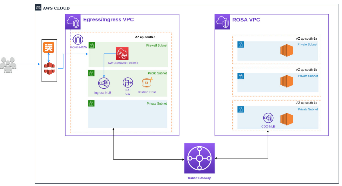
The network details used in this architecture are:
- Egress/Ingress VPC (10.0.0.0/16)
- Egress public subnet (10.0.128.0/19)
- Egress public subnet (10.0.0.0/17)
- Firewall subnet (10.0.192.0/27)
- ROSA VPC (10.1.0.0/16)
- ROSA subnet 1 (10.1.0.0/18)
- ROSA subnet 2 (10.1.64.0/18)
- ROSA subnet 3 (10.1.128.0/17)
The AWS network firewall will be created in the firewall subnet which will specify the VPC endpoint in the route table entries shown in Figure 2.

Log in to the jump host from where you have access to the ROSA cluster.
Configure custom domain for applications
To configure a custom domain for applications, get the certificates for your custom domain. If you don’t have one, you can generate the certificates using certbot as follows:
$ oc new-project custom-domain

$ EMAIL=testuser@gmail.com

$ DOMAIN=sgaikwad.mobb.ninja

$ certbot certonly --manual --preferred-challenges=dns --email $EMAIL --server https://acme-v02.api.letsencrypt.org/directory --agree-tos --manual-public-ip-logging-ok -d "*.$DOMAIN"
Follow the instructions to create a TXT record in route53. This will create certs in /etc/letsencrypt/live/sgaikwad.mobb.cloud-* directory. Specify the exact path as follows:
$ CERTS=/etc/letsencrypt/live/sgaikwad.mobb.cloud-*

$ oc create secret tls acme-tls --cert=$CERTS/fullchain.pem --key=$CERTS/privkey.pem

$ cat cr.yaml

apiVersion: managed.openshift.io/v1alpha1

kind: CustomDomain

metadata:

  name: acme

spec:

  domain: sgaikwad.mobb.cloud

  scope: Internal

  loadBalancerType: NLB

  certificate:

    name: acme-tls

    namespace: custom-domain

$ oc apply -f cr.yaml
Wait until customdomain has endpoints.
$ watch oc get customdomains
This will create a network load balancer in the ROSA VPC. Let's create a network load balancer in Egress/Ingress VPC now.
Create a target group as follows:
$ export ROSA_EGRESS_VPC=<VpcId_for_Egress_VPC>

$ export TG_NAME=rosa-tg1

$ export ROSA_EGRESS_VPC=`aws ec2 describe-vpcs  --filters Name=tag:Name,Values=rosa-egress-vpc |jq -r.Vpcs[0].VpcId`

$ export TG_ARN=$(aws elbv2 create-target-group --name test --protocol TCP --port 80 --vpc-id $ROSA_EGRESS_VPC --target-type ip --ip-address-type ipv4 --query 'TargetGroups[0].TargetGroupArn'  --output text)
To get the target_Id from your OpenShift Service on AWS cluster, enter the following:
$ export NLB_PRIVATE_IP=`nslookup $(oc get customdomains |awk '{print $2}' |tail -1) |grep Address: |grep -v '#' |awk '{print $2}'`
Register targets for your Target Group as follows:
$ aws elbv2 register-targets --target-group-arn $TG_ARN --targets AvailabilityZone=all,Id=$NLB_PRIVATE_IP,Port=80

$ aws elbv2 register-targets --target-group-arn $TG_ARN --targets AvailabilityZone=all,Id=$NLB_PRIVATE_IP,Port=443
Next, create a network load balancer in Egress/Ingress VPC by grabbing the public subnet IDs from the VPC connected to the internet and map it while creating the load balancer as follows:
$ export SUBNET_ID=`aws ec2 describe-subnets --filters "Name=vpc-id,Values=$ROSA_EGRESS_VPC" --filters "Name=tag:Name,Values=rosa-egress-public-subnet"  --query 'Subnets[*].SubnetId' --output text`

$ export NLB_ARN=`aws elbv2 create-load-balancer --name sgaikwad-rosa-nlb --type network --scheme internet-facing --subnet-mappings SubnetId=$SUBNET_ID --query 'LoadBalancers[0].LoadBalancerArn' --output text`
Now, let's create a listener and default action as follows:
$ aws elbv2 wait load-balancer-available --load-balancer-arns $NLB_ARN && export NLB_LISTENER=$(aws elbv2 create-listener --load-balancer-arn ${NLB_ARN} --port 80 --protocol TCP --default-actions Type=forward,TargetGroupArn=${TG_ARN} --query 'Listeners[0].ListenerArn' --output text)

$ aws elbv2 wait load-balancer-available --load-balancer-arns $NLB_ARN && export NLB_LISTENER=$(aws elbv2 create-listener --load-balancer-arn ${NLB_ARN} --port 443 --protocol TCP --default-actions Type=forward,TargetGroupArn=${TG_ARN} --query 'Listeners[0].ListenerArn' --output text)
Add CNAME record in route53 to point to the newly created internet-facing NLB by grabbing the DNS name for the newly created NLB as follows:
$ export NLB_DNS_NAME=`aws elbv2 describe-load-balancers --load-balancer-arns $NLB_ARN --query 'LoadBalancers[0].DNSName' --output text`
Go to route53 and select your domain by following these steps. (In my case, it’s mobb.cloud.)
- Click on Create Record.
- Under record name, specify your domain:
*.sgaikwad.mobb.cloud - Select CNAME for record type.
- In the value field, enter the value:
$NLB_DNS_NAME - Click Create Record.
How to implement AWS network firewall
With the network firewall, you can filter traffic at the perimeter of your VPC. This includes filtering traffic moving to and from an internet gateway, NAT gateway, or over a VPN or AWS Direct Connect. To create a firewall via the console, you need to create a separate subnet where you want to deploy the AWS network firewall. We recommend creating a separate subnet for the firewall because the AWS network firewall can’t inspect the packets originating and targeting from the same subnet. Hence, if you have any other EC2 instances running in the same subnet, the packets won’t be inspected by the AWS network firewall.
$ EGRESS_FIREWALL_SUBNET=`aws ec2 create-subnet --vpc-id $ROSA_EGRESS_VPC --cidr-block 10.0.192.0/27 | jq -r.Subnet.SubnetId`

$ aws ec2 create-tags --resources $EGRESS_FIREWALL_SUBNET --tags Key=Name,Value=firewall-subnet
Create a firewall rule group
Create a firewall rule group that defines what actions to perform on the packets which will be inspected by the firewall. In this example, we will create a stateless firewall rule group.
- Sign in to the AWS Management Console and open the Amazon VPC console at https://console.aws.amazon.com/vpc/.
- In the navigation pane, under Network Firewall, choose Network Firewall rule groups.
- Choose Create Network Firewall rule group.
- On the Create Network Firewall rule group page, for the Rule group type, choose Stateless rule group.
- Enter a name and description for the rule group. You'll use these to identify the rule group when you manage and use it.
- For Capacity, set the maximum capacity you want to allow for the stateless rule group, up to the maximum of 30,000. You can't change this setting after you create the rule group. For information about how to calculate this, refer to: Setting rule group capacity in AWS Network Firewall. Set the capacity to 10.
- Review the rules that you want to add to the stateless rule group. Click on Add rule. We will add a rule to allow SSH traffic from your IP and block it for all others as an example.
- Specify the priority to 1.
- Choose TCP and UDP under protocol.
- Under source, select any IPV4 address and enter your public IP address. For source port range, select Any.
- Select Custom in the destination field and specify 0.0.0.0/0 for destination. Specify port 22 in the destination port range.
- Under actions, select Pass and create the rule.
- Repeat the above steps to block SSH traffic to everyone else. Specify priority 2 and 0.0.0.0/0 in the source field and Drop in the actions field.
- Review the settings for the rule group, then choose Create stateless rule group.
Create a firewall policy
Create a firewall policy by following these steps:
- Sign in to the AWS Management Console and open the Amazon VPC console at https://console.aws.amazon.com/vpc/.
- In the navigation pane, under Network Firewall, choose Firewall policies.
- Choose Create firewall policy.
- Enter a Name to identify this firewall policy.
- For Stream exception policy, choose how the network firewall handles traffic when a network connection breaks midstream. Network connections can break due to disruptions in external networks or within the firewall itself. Choose Continue.
- Choose Next to go to the firewall policy's Add rule groups page.
- Keep the settings at default and click on Add Stateless rule groups.
- Select the rule you created earlier and click on Add rule Group.
- Keep all other settings at default and create the firewall policy.
Create the network firewall
Once the firewall policy is created, create the network firewall as follows:
- Sign in to the AWS Management Console and open the Amazon VPC console at https://console.aws.amazon.com/vpc/
- In the navigation pane, under Network Firewall, choose Firewalls.
- Choose Create firewall.
- Enter a name to identify this firewall.
- Choose your VPC from the dropdown list. Here, choose ROSA Egress VPC.
- For Firewall subnets, choose the availability zones and subnets that you want to use for your firewall endpoints. Select the newly created Firewall subnet from the list.
- For the Associated firewall policy section, choose the firewall policy that you want to associate with the firewall. Select the firewall policy we created in the previous step.
- Select Create firewall.
Configure VPC route tables
Now, configure your VPC route tables to send traffic through the firewall endpoints. For more information, refer to VPC route table configuration for AWS Network Firewall.
Create a new route table to route all the incoming and outgoing traffic through firewall. Under VPC, from the route tables page, click Create Route Table.
- Specify a name for your route table (i.e., FirewallRT).
- Select the Egress VPC and click on create Route table.
- Select the newly created subnet and click on subnet associations from the bottom menu.
- Click on Edit subnet association and select Firewall Subnet.
- Then, click on the Routes and add two routes as follows:
- For destination 0.0.0.0/0, the target would be the Internet gateway associated with Egress VPC.
- For destination 10.0.0.0/16, the target would be local.
- Similarly, create a new route table for the internet gateway. Specify the name InternetGwRT.
- Select Egress VPC and click on create route table.
- Select the InternetGwRT from the list and click on Edge Associations.
- Attach the internet gateway by clicking on Edit Edge Associations.
- Click on the routes and add the following two routes:
- For destination 10.0.128.0/19, the target would be VPC endpoint which was created after creating the network firewall. Verify the VPC endpoint for the firewall from the endpoints section under VPC.
- For destination 10.0.0.0/16, the target would be local.
- Now, select the rosa-egress-public-rt route table and verify the following three routes. If any routes are missing, create those.
- For destination 0.0.0.0/0, the target would be VPC endpoint which was created after creating the Network firewall.
- For destination 10.0.0.0/16, the target would be local.
- For destination 10.1.0.0/16, the target would be transit gateway (rosa-egress-tgw-attachment).
Create WAF and cloudfront distribution
- Create a WAF rule here: https://console.aws.amazon.com/wafv2/homev2/web-acls/new?region=us-east-2
- Specify the name for your web ACL.
- Select Amazon CloudFront distributions in the resource type and click next.
- Click on Add rules and select Add Managed Rule groups from the list.
- Use the core rule set and SQL injection rules from the free rule groups.
- Click Review and Create.
- Add a certificate to ACM: https://us-east-2.console.aws.amazon.com/acm/home?region=us-east-1#/importwizard/
- Click on import and paste in the cert, key, certchain from the files which we have generated earlier for the custom domain. Click Review and Create.
- Log into the AWS console and Create a Cloud Front distribution (make sure it's the same region as your cluster).
- Click on Create distribution.
- In Origin Domain Name, select sgaikwad-rosa-nlb (the network load balancer you created in Egress VPC).
- Select Origin Protocol Policy: HTTPS only.
- For Enable Origin Shield, click on yes. Specify ap-south-1 as origin shield region.
- Set the viewer protocol policy to Redirect HTTP to HTTPS.
- Set the Allowed HTTP Methods to GET, HEAD, OPTIONS, PUT, POST, PATCH, DELETE.
- Under Cache key and origin requests, for Cache Policy, select CachingDisabled.
- For the Origin request policy, click on Create Policy and specify the name for your policy.
- Under Origin request settings, select Allow viewer headers, All query string and all cookies. Click on Create.
- Select sgaikwad in AWS WAF web ACL (the web ACL which we created in previous step).
- Under Alternate domain name (CNAME), click on Add item and use *.sgaikwad.mobb.cloud as a domain. Replace this with your domain.
- Under Custom SSL certificate, select the domain you uploaded the certificate in ACM.
- Click on create distribution.
- Under the details page for your distribution, check Distribution domain name and copy it.
- Modify the route53 CNAME record to point to the cloud front distribution instead of Egress NLB.
- Under services, go to Route53 hosted zones.
- Select your hosted zone. For me, it’s mobb.cloud.
- Select *.sgaikwad.mobb.cloud CNAME record, click on Edit and change the value to the Cloudfront distribution domain name value that you copied in the previous step.
Deploy the application
Now that we have configured all the components, we are all set to deploy the sample application in the ROSA cluster and access it from the internet by creating a route with the domain name.
$ oc new-project application

$ oc new-app --docker-image=docker.io/openshift/hello-openshift

$ oc create route edge --service=hello-openshift hello-openshift-tls --hostname hello-openshift.sgaikwad.mobb.cloud
Now, open the browser from your local system and access the application with https://hello-openshift.sgaikwad.mobb.cloud.
Learn more
If you have questions, please comment below. We welcome your feedback. Visit Red Hat OpenShift Services on AWS (ROSA) for more information and resources.
Last updated: September 19, 2023