Businesses are seeking to benefit from every customer interaction with real-time personalized experience. Targeting each customer with relevant offers can greatly improve customer loyalty, but we must first understand the customer. We have to be able to draw on data and other resources from diverse systems, such as marketing, customer service, fraud, and business operations. With the advent of modern technologies and agile methodologies, we also want to be able to empower citizen integrators (typically business users who understand business and client needs) to create custom software. What we need is one single functional domain where the information is harmonized in a homogeneous way.
In this article, I will show you how to use Red Hat Integration to create a personalized customer experience. Figure 1 shows a high-level overview of the integration architecture we'll use for the example.

Let's start by looking at the use case for a Loyalty Management application; then, I'll introduce the technologies we'll use for the integration.
Loyalty Management Use Case
Our example application fulfills a use case of sending offers to customers in realtime. When a customer performs a transaction, it enters the event stream. For every event, we fetch the customer context and perform two simple checks:
- Is the customer a
PLATINUMorGOLDuser? - Is the customer's predictive loyalty segmentation
HIGHorMEDIUM?
We'll then use this information to determine whether to extend an offer to the given customer.
Architectural overview
Red Hat Integration is a set of integration and messaging products that provide API connectivity, data transformation, service composition, and more. For the example application, we'll use Red Hata Data Virtualization, Red Hat Fuse Online, and Red Hat AMQ Streams. Figure 2 shows the architecture and technologies used by our architecture.

We will use Red Hat Integration for both its event streaming infrastructure and its ability to fulfill the required integration capabilities. The architecture's backbone is Red Hat AMQ Streams, a massively scalable, distributed, and high-performance data-streaming platform that is based on Apache Kafka.
We'll also use the developer preview of Red Hat Data Virtualization, a container-native service that provides integrated access to diverse data sources. We'll use Data Virtualization to collect data from different data sources. We'll use the data to create the customer context.
Finally, we'll use Red Hat Fuse Online to create both the integration and the data services. Fuse Online is an Integration Platform-as-a-Service (iPaaS) that makes it easy for business users to collaborate with integration experts and application developers. With Fuse Online's low-code tooling, integration experts can quickly create data services and integrations.
The Integration flow
Figure 3 shows the sequence of steps required for the example integration.
The integration begins when the system reads an event from a Transaction topic. The system looks up the customer's context and Customer Segmentation. The system then applies checks to ensure that only users who meet the required filter criteria will receive an offer. Finally, if the customer is eligible, the system publishes an offer in a secondary Kafka topic.
Preparing the environment
Now that you have an overview of the example integration let's set up our demonstration environment. We'll use Red Hat OpenShift to install the components that we need. OpenShift enables efficient container orchestration, allowing developers to rapidly provision, deploy, scale, and manage container-based applications. We'll use Red Hat Integration on OpenShift to rapidly and easily create and manage a web-scale cloud-native integration.
Step 1: Deploy AMQ Streams
To start, we'll install AMQ Streams from the OpenShift OperatorHub. Begin by logging in to the OpenShift console and creating a new project. Figure 4 shows the selection to install the AMQ Streams Operator from the OperatorHub.

Next, create a Kafka cluster with the default settings provided by the AMQ Streams Operator, as shown in Figure 5.
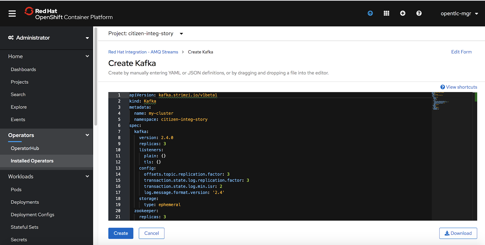
You should now have an ephemeral Kafka cluster.
Step 2: Deploy Fuse Online
Now we'll use the OperatorHub to deploy Fuse Online, as shown in Figure 6.

Step 3: Prepare the data
The final step before we begin the demo is to create the database tables that will hold our application's customer and transaction data. We will need to set up a mock event emitter that would mimic the behavior of real customer events flowing through the system. We will also need to set up a mock endpoint for the prediction service, which we'll consume from our integration service. This part of the process is a little more involved, so please follow the steps described here to complete the setup.
Low-code tooling with Fuse Online
Once the infrastructure is set up, we can log in to the Fuse Online console. You can find the URL for the console under the routes. You should be able to log in with your OpenShift console credentials.
Step 1: Create connections
First, we'll need to set up two connections: one for the PostgreSQL database and the other for MySQL. From Fuse Online's Connections tab, click on Create Connections and choose Database, as shown in Figure 7. Setup the connection credentials for the Postgres DB.

Follow the same process to create the connection string for the MySQL database, using the connection parameters shown in Figure 8.

The Kafka connector
Next, we'll create a Kafka connector so that we can read and publish events to a customer events stream. Choose the Kafka Message Broker connection type under Create Connections, then add the URL of the previously created Kafka cluster, as shown in Figure 9.

The API client connection
Finally, we'll set up an API client connection to mock the prediction API. Upload this JSON file to create the prediction-service connector, as shown in Figure 10.

Follow the directions to save the API client connector when you are done.
Now we're ready to begin creating the integration. We'll start with the data service.
Step 2: Create the data service
Start by selecting the Data option from Fuse Online's left-hand pane, then click on Create Data Virtualization.
Create a view
All of our connections appear in the view editor. Select the Transaction and Customer tables, as shown in Figure 11.

We can also use the view editor to create a Virtual Database table with the consolidated customer context, as shown in Figure 12.

The view editor also provides a data section where we will be able to test the results of a query.
Publish and access the data service
Now we are ready to publish the data service. Once it's published, we can use either the Java Database Connectivity (JDBC) API or an OData endpoint to access the virtual database. Select the OData endpoint, as shown in Figure 13.

As shown in Figure 14, we can use the URL format <odata-link>/odata/<virtualization-name>/<view-name> to access the OData endpoint.

Step 3: Create the integration service
Now we'll create an integration service.
Subscribe and Publish to Kafka
In the Fuse Online console, go to the Integration tab and click Create Integration. As shown in Figure 15, we can read from the Kafka topic where customer events are created.
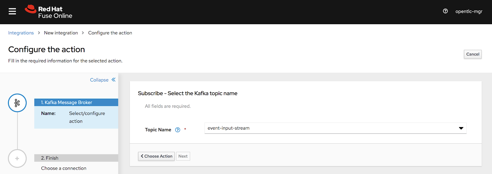
We'll use a JSON instance to define the message's data structure:
{"eventValue": "MERCHANDISE", "eventSource": "POS","custId":"CUST898920"}
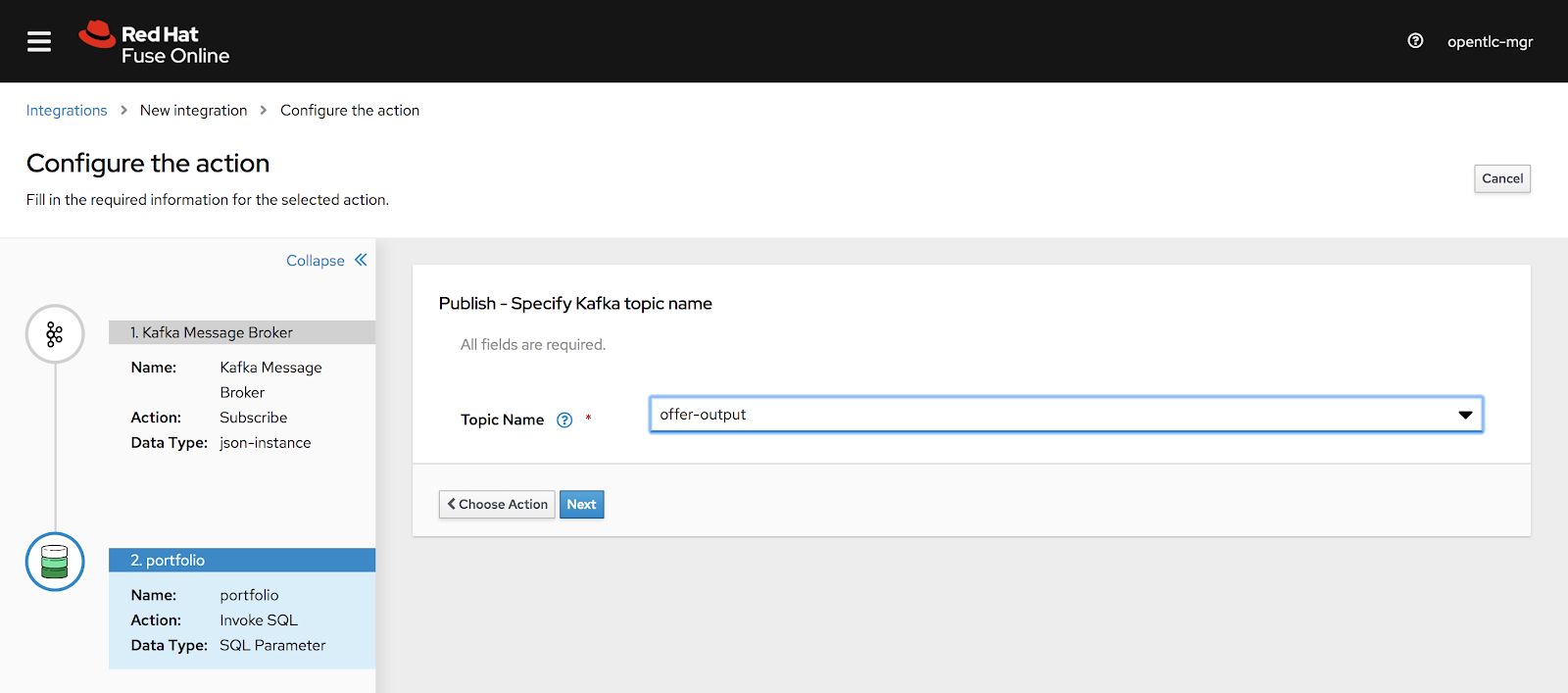
As shown in Figure 16, we'll define the integration's last step, where we'll write the offer results back to a Kafka topic. We will define the JSON instance for the customer's offer data, as follows:
{"offer": "value", "custId":"id","customerClass":"class","customersegmentation":"segment"}
Fetch the customer data
Next, we fetch our customer data from the virtual database. In the Fuse Online console, select the Virtual DB connection that we configured earlier, then choose the Invoke SQL option.
Next, we'll define intermediate steps before reaching that endpoint. For every customer record, we will fetch the customer's virtual data context, which we created earlier. Figure 17 shows the dialog to fetch the virtual data context.

Figure 18 is a screenshot of how the integration looks so far.

Fetch the prediction data
Next, we'll add a step to fetch the prediction data from our mock prediction service. Click on the plus (+) symbol after Step 2 and choose the prediction-service connection that we created earlier. This step is shown in Figure 19.

Define a data mapper for each connection
After each of the connection steps, you will now see a warning to define the data mapper. The data mapper maps a customer's input values to the correct output values. To start defining the data mappers, click on the plus (+) symbol immediately after Step 1. As shown in Figure 20, this will give you the option to define the target step.

Follow the same process to define the mapper that will be called when we invoke the prediction service, and then the mapper that will be called before we publish to the Kafka topic.
As shown in Figure 21, we use the data-mapper dialog to map the values from each of the steps so that we can select the correct offer for the customer. Also, note that we are using this dialog to add a transformation to the offer text.

Step 4: Apply the filter criteria
We've used Fuse Online to connect all the pieces of our integration. However, you might have noticed that we are missing an important piece. Before we can publish our integration, we need to ensure that we will only extend an offer to customers who have a PLATINUM or GOLD status, and whose predictive loyalty segmentation is labeled either HIGH and MEDIUM. For this, we will configure the Basic Filter option shown in Figure 22.

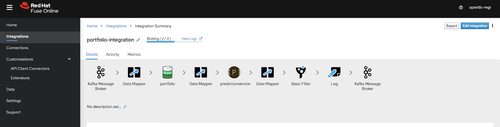
Step 5: Publish and monitor the integration
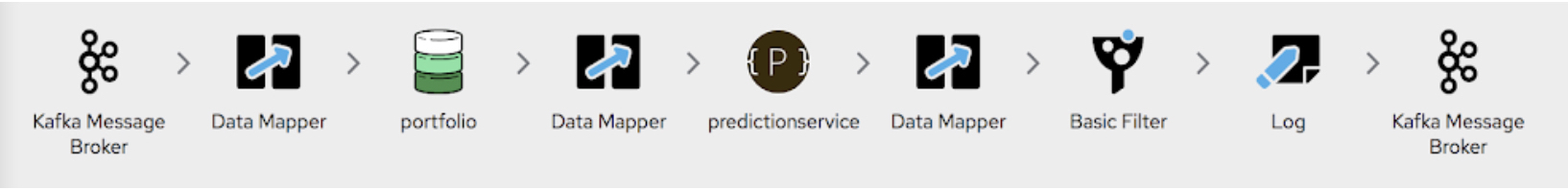
Now that we are done assembling all of the pieces, it is time to publish. Just save the integration and publish it. After it is published, the integration stack should look like what you see in Figure 23.
Monitor the integration
We can use the Activity tab to view events as they are being processed, as shown in Figure 24.

We can use the Metrics tab to view the overall metrics for processed messages, as shown in Figure 25.

Visit my GitHub repository to download the complete integration code. If you want to import the code to Fuse Online, navigate to the Integration tab, and click Import.
Summary
Using the data-first approach, we are now able to quickly visualize the context information required for our near real-time processing requirements. By providing low code tooling we are able to empower the citizen integrators and data experts to quickly create these integration solutions in a cloud-native fashion.
Last updated: June 25, 2020
