The Raspberry Pi Model B was released in 2012 and, since then, a number of useful applications regarding this device have ensued. However, one particular application that is seldom overlooked when dealing with the Raspberry Pi is its ability to be used as a Stratum 1 NTP server and allow you to synchronize clocks across networks like the Internet. For me, this useful trick has actually made my entire office far more efficient.

What is Stratum 1 NTP?
Although many of you are probably already well aware of what NTP is and what is does, it never hurts to refresh yourself on the subject before beginning a project. With this said, Network Time Protocol (NTP) is used to synchronize computer clock times in a network of computers. By using Coordinated Universal Time (UTC), NTP is capable of synchronizing computer clocks to the millisecond, or in some cases, even fractions of a millisecond.
By doing this, you can create a primary time server that is connected to the receiver and synchronize clock times of computers within a network rather than being forced to outfit each computer with specialized receivers individually. This creates a cost-effective alternative that still allows you to reap the many benefits of UTC without the hassle and price commonly involved.
The degree in which these computers are connected to the UTC source is defined by strata. A Stratum 1 NTP Server, in particular, is directly connected to the radio clock that receives the actual true time from a satellite navigation system or dedicated transmitter whereas Stratum 2 connects to the Stratum 1 computer and so on and so forth.
How is NTP Useful?
NTP servers create a cost-effective way to still receive a UTC source’s true time and reap the benefits of computer synchronization in various fields of their company. For instance, when you are troubleshooting a particular site, synchronization is highly important in order to evaluate server logs, as SSL requires that the time on your computer be synchronized to the time of the server you are connected to on your browser.
Similarly, distributed procedures rely on coordinated times to ensure that proper sequences are followed and security platforms equally rely on this synchronization in order to encrypt data, create complex authentication systems, and improve data entry and conversion without running the risk of cyber security threats or financial fraud. Another process, which relies on clock synchronization, is file system updates that include a number of computers carrying out the procedure accordingly. Lastly, when using data encryption or recovery systems like Kali Linux and KrolLDiscovery for security management, it is vital to have your NTP set accurately in order to ensure procedures are done correctly. Once this is completed, you can protect yourself against data breaches and find flaws in your current security systems likewise. By setting up a Stratum 1 NTP Server for a little over $100, you can improve workflow and reap the benefits of UTC in the office accordingly.
What You Will Need to Build Your Stratum 1 NTP Server: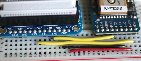
- A Raspberry Pi (preferable Model B with 512 MB of Ram)
- A GPS module with PPS Output (Preferably Adafruit’s Ultimate GPS Breakout)
- CR1220 Replacement Battery
- Premium Male/Male Jumper Wires
- GPS Antenna
- Case/ Enclosure for Raspberry Pi
- SMA to uFL/u.FL/IPX/IPEX RF Adapter Cable
- Half-Size Breadboard
- Optional: Chronodot (the Raspberry Pi does not come with a hardware clock and the Chronodot installation is an efficient way to resolve that issue)
- Adafruit Assembled Pi Cobbler Breakout and Cable for Raspberry Pi
How to Setup the Hardware
The first thing you will need to do is connect all of the puzzle pieces together. In order to do this, you must connect the GPS/PPS output to pin number 23 on the Pi. Next, you will need to connect the GPS TXD to the Raspberry Pi RXD. 5V power to VIN, and GND to GND. If you are specifically looking to troubleshoot, you can also connect another cable from the GPS RXD to the Raspberry Pi TXD.
Next, apply the breadboard to the Raspberry Pi case using its sticky adhesive and solder the breadboard breakout pins to the GPS breakout board. After that, you will also need to solder the battery house as well. For me, I have worked with soldering multiple times on other projects but if this is something new to you, you may want to take some time in order to not destroy any of the sensitive hardware.
How to Set Up the Operating System
The first step in setting up the OS is to install Adafruit’s Occidentalis v0.2 image as it comes with additional packages already installed that Raspbian does not. Once you have downloaded the image, write it to an SD card:
#dd if=/path/to/occidentalis.img of=/dev/sdz
Next, you’ll want to SSH to it as soon as possible (trust me, it’s easier). To do this, mount the SD card and edit the “/etc/network/interfaces” file. After you have completed this, you will want to set up the virtual interface (here’s an article on how to do that). Next, when booting up the Raspberry Pi, insert an Ethernet cable from your laptop or desk computer to your Pi and SSH it directly.
Once you’ve reached this point, you will now need to install a custom kernel, as the default kernel that is shipped with Raspbian does not support PPS. To do this, I referenced another individual’s 3.1 kernel repository.
First, open up a terminal and as root, install Git and then use this repository:
#apt-get install git
#git clone https://github.com/davidk/adafruit-raspberrypi-linux-pps.git
Next, copy over the new kernel and kernel modules:
# cd adafruit-raspberrypi-linux-pps
# cp kernel.img /boot/kernel.img.pps
# cp -a modules/* /lib/modules
By making it persistent, you can ensure the “pps-gpio” module is loaded on each boot. Next, run the following command to add it to the “/etc/modules” configuration file:
# echo ‘pps-gpio’ >> /etc/modules
Now, you want the “/boot/config.txt” to reflect the new kernel so modify it by adding this at the end of that file:
kernel=kernel.img.pps
gpu_mem=16
Once this is completed, you can finally reboot and verify you are in the right kernel with a properly loaded “pps-gpio” module using:
# uname -a
Linux ntp.example.com 3.1.9adafruit-pps+ #21 PREEMPT Sun Sep 2 10:57:58 PDT 2012 armv6l GNU/Linux
# lsmod | grep pps-gpio
pps_gpio 2314 0
pps_core 7808 2 pps_gpio,pps_ldisc
How to Compile NTP
So, you’ve finished setting up the hardware and OS but now it is time to compile NTP. Because the original Raspbian package does not have ATOM support, you will need to custom-compile NTP. In order to do this, pull up a terminal, and as root, edit the “/etc/apt/sources.list” file by adding the following line:
deb-src http://mirrordirector.raspbian.org/raspbian/ wheezy main contrib non-free rpi
Then, type the following commands in the terminal as root:
# apt-get update
# apt-get build-dep ntp
# apt-get source ntp
# cd ntp-4.2.6.p5+dfsg
Here’s where things get good; modify the “debian/rules” file, and add “- - enable-ATOM” to the configure statement. Then, modify the “debian/changelog” file by appending “pps” to the proper version number. Once this is complete, you will need to install and build the package:
# dpkg-buildpackage -b
# cd ../
# dpkg -i ntp_4.2.6.p5+dfsg-2pps_armhf.deb ntp-doc_4.2.6.p5+dfsg-2pps_all.deb
How to Configure NTP
The Adafruit GPS module is a generic NMEA GPS and, therefore, uses driver 20. Because of this, you must add the following lines to the “/etc/ntp.conf” configuration file:
server 127.127.20.0 mode 17 noselect
fudge 127.127.20.0 flag1 0 time2 0
Once this is complete, your GPS clock will be set to “noselect” allowing you to figure out the accurate time for “time2” to fudge. Because it does take a while for the time to be received by the NTP due to the signal. You will want to run your NTP for 24 hours and modify the “/etc/ntp.conf” file as well as change “noselect” to “iburst” and enable PPS processing to make the necessary changes. Once this is complete, you can restart your NTP.
Let the NTP run for a while and then take into account leap seconds to adjust the clock as necessary. To do this, create the following shell script. Then, install it into “/usr/local/bin/leap-seconds.sh”:
#!/bin/sh
cd /etc/ntp
wget ftp://time.nist.gov/pub/leap-seconds.list &> /dev/null
service ntp restart &> /dev/null
Now, you must create an entry in root’s crontab (5):
0 0 31 6,12 * /usr/local/bin/leap-seconds.sh
Once this is done, you must make sure it is executable:
# chmod a+x /usr/local/bin/leap-seconds.sh
Lastly, modify the “/etc/ntp.conf” configuration file one again, and add this at the top of the file:
# leap seconds file
leapfile /etc/ntp/leap-seconds.list
At this point, you can finally restart NTP. Now, if you are looking to connect and synchronize multiple computers, you may want to configure other active servers as well in your “/etc/ntp.conf” configuration file. When doing this, you can simply add additional servers at the bottom of the file. However, keep in mind that the further away from the UTC source each stratum is, an additional 60 microseconds is added.
Although building this Stratum 1 NTP server can be time-consuming and difficult to do properly, it is most certainly worth the effort. Using this NTP server not only can save you a tremendous amount of money but also help you to execute some of the things you have not been able to do or haven’t been able to do efficiently in the past. Although the Raspberry Pi continues to release countless models and boards, it is sometimes a good idea to simply stick to the basics and create some amazing affordable tech in the process.
Last updated: May 31, 2024