In Disaster recovery approaches for Red Hat OpenShift Virtualization, we laid the foundation for disaster recovery by exploring how cluster topology, storage architecture, and replication strategies underpin service availability. In this follow-up post, we take the next step: orchestrating application failover using Kubernetes-native constructs and GitOps workflows. Here, disaster recovery (DR) becomes less about where data lives, and more about how workloads are redeployed, prioritized, and verified in the face of disruption—bringing declarative control, automation and auditability to the operational layer.
Orchestrating virtual machine failover with Kubernetes and GitOps
Having previously established how unidirectional and symmetric volume‑replication patterns (together with their associated cluster topologies) protect data, we can now shift focus from the underlying infrastructure to the workloads themselves. The architectural foundations we have discussed thus far guarantee that the virtual machine (VM) disks remain available, yet they say little about where individual VMs should run, in what order they restart, or how human operators coordinate these actions during a crisis.
Bridging this gap requires an application‑centric view of disaster recovery—one that treats failover as a controlled placement activity governed by Kubernetes features and higher‑level automation. The following section shifts our perspective from storage replication to application failover, exploring how Node Selectors, tolerations, and Red Hat Advanced Cluster Management placement rules work in concert alongside tools such as Ansible, Helm, and Kustomize to direct workloads to the appropriate site at the right time while preserving human oversight.
The general requirements for a disaster recovery process are the following:
- The DR strategy must account for the entire DR orchestration, failover, failback, and all other intermediate states.
- It should be possible to initiate the DR process for individual applications as well as for groups of applications (usually referred to as tiers of applications).
- It should be possible to conduct DR exercises or rehearsals on a regular basis to verify that the DR process actually works.
Let’s analyze how to orchestrate DR-related activities within the two architectural approaches that we have described previously.
Disaster recovery process in a dual-cluster topology
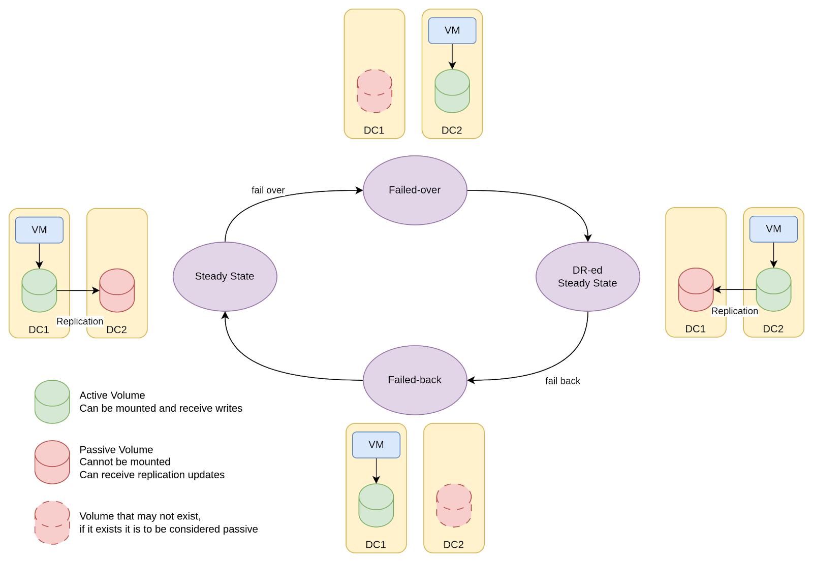
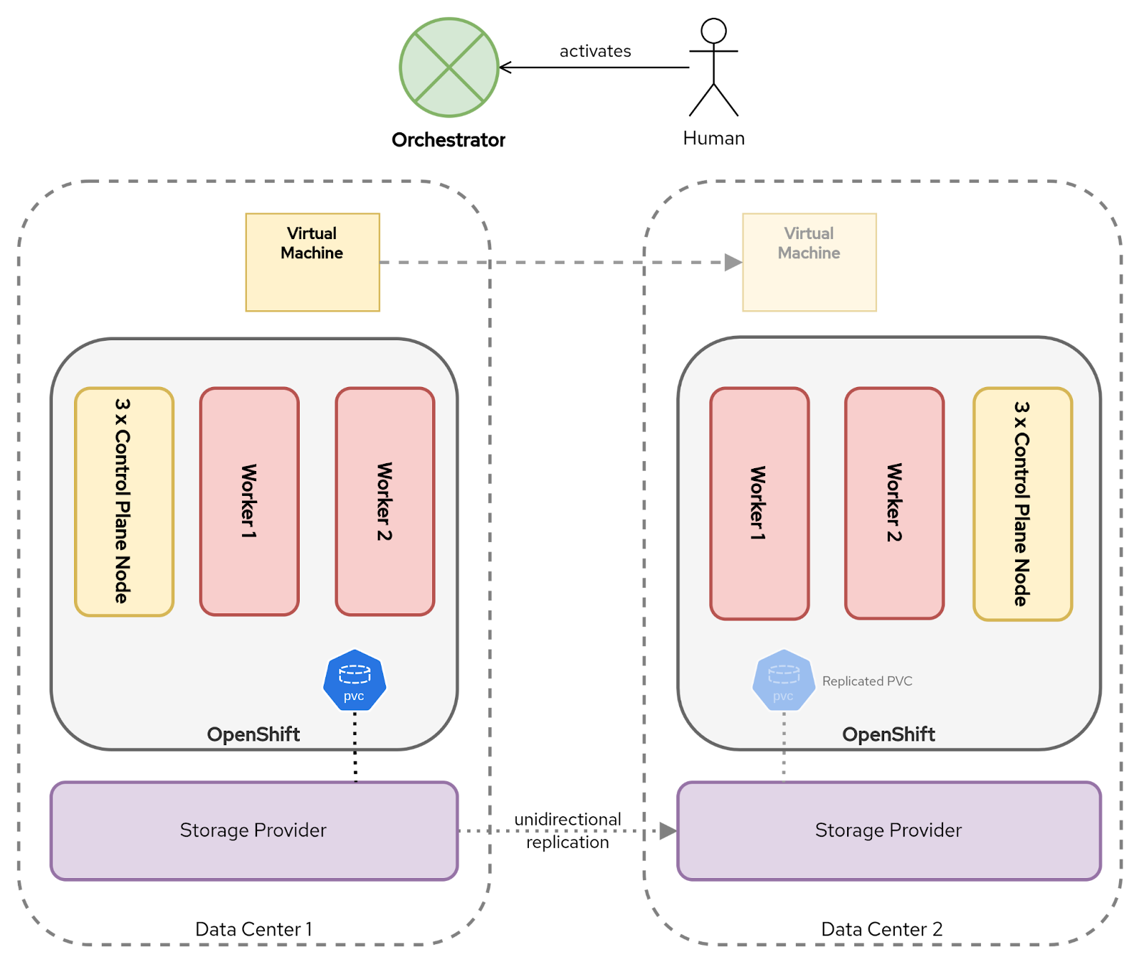
In a dual‑cluster topology, corresponding to a unidirectional volume replication pattern, a DR lifecycle is depicted in Figure 1.

Within this diagram, the following stages are illustrated::
- In the steady state, VMs run in the primary site and volumes are replicated to the secondary site.
- In the failover state, the PVs and PVCs for a VM are created or preexist in the DR site and the VM is started in the DR site attaching to the correct volume. Since the volume was being replicated, it is ready for immediate use.
- When the failed site is recovered, volumes from the DR site are set to be replicated back to the primary site. This state is akin to the steady state.
- To return to the steady state, a failback needs to occur. In the failback state, the replication from DR site to primary site is interrupted and the VMs are started and attached to the volumes in the primary site.
As discussed earlier, many enterprise storage platforms provide increasing levels of maturity to take the complexity out of multicluster application failover. Let’s analyze what needs to occur in order to create the corresponding DR process depending on the level of maturity:
- No support for VolumeReplication by the CSI driver: The DR automation will have to communicate with the storage array API to manage the state of the volumes and with the OpenShift API to manage PV, PVCs, and VMs.
- VolumeReplication supported by the CSI: Typically, these vendors have a way to streamline the creation of the PV and PVC on the passive site. The PVC/PV, therefore. awaits being attached to the SAN volume and can be referenced by name without modification. This capability dramatically simplifies the migration of the VM to the alternate site. However, it is still the OpenShift administrator's responsibility to manage the VMs themselves.
VolumeReplication and namespace metadata supported by the storage vendor: Some storage platforms extend beyond PVC replication and also synchronize the associated Kubernetes objects—effectively bridging the gap between infrastructure replication and GitOps-style application management.
These platforms automatically reconstruct application state, including custom resources, like VirtualMachines, ConfigMaps, and Secrets, at the recovery site. This approach shifts responsibility of the DR orchestration into the storage layer itself, offering an alternative to pure GitOps-driven workflows or enhancing them with greater automation and reduced dependency on upstream automation.

Disaster recovery process in a single-cluster topology
In a single‑cluster topology, the two datacenters share a common Kubernetes control plane and a symmetric-replication storage fabric. This architecture enables disaster recovery as an intra‑cluster placement exercise rather than a cross‑cluster redeployment.
You might decide to let VMs float between the two sites. But, in practical terms, doing so will introduce a number of additional complexities that must be considered. For example:
- A VM might be dependent on local services or databases that exist only in one site.
- Allowing VMs to float freely might generate a Restart Storm when multiple nodes become unavailable at the same time.
- In the steady state, allowing the KubeVirt scheduler to freely live migrate VMs between sites (e.g., when you drain a node to upgrade your cluster) comes with the requirement to migrate the VM's memory to the alternate site, potentially stressing your network as gigabytes-to-terabytes of data is copied across sites.
Assuming there is a goal is to control which site a VM is scheduled to run in, Kubernetes actually provides the necessary levers through its native capabilities, such as node labels and selectors, taints and tolerations, affinity/anti‑affinity rules, and topology‑spread constraints.
Grounding the fail‑over strategy in these native primitives capitalizes on Kubernetes’ reconciliation loop, thus avoiding bespoke scripts or external orchestrators. The workflow stays declarative, idempotent, and version‑controlled, enabling the same mechanisms that handle everyday scheduling of workloads within Kubernetes to also enforce disaster‑recovery policies. Benefits include fewer moving parts, smoother upgrades, built-in observability, and a shorter recovery time.
The choice of which Kubernetes feature that should be used to control the failover process is one of simplicity over flexibility. Node Selectors are relatively simple to understand and implement. But, other features, such as taints and tolerations, provide increased flexibility in managing the failover activities. For simplicity, we will limit this discussion to Node Selectors.
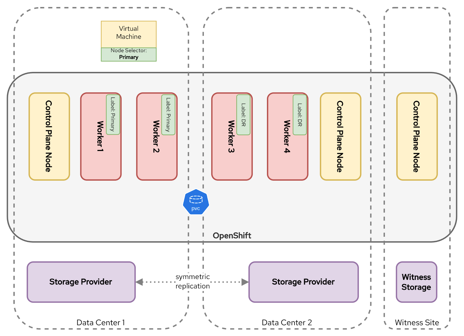
With Node Selectors, a consistent label (e.g., Primary in the main site and DR in the secondary site) is applied on every worker node, e.g.:
Node label at Primary site:
metadata:
  label:
    topology.kubernetes.io/site=Primary
Node label at DR site:
metadata:
  label:
    topology.kubernetes.io/site=DR
When creating a VM, a nodeSelector is defined with a value that matches the worker node label at the desired site. For example:
spec:
  template:
    spec:
      nodeSelector:
        topology.kubernetes.io/site: Primary
As illustrated in Figure 3, Kubernetes will then ensure that when the VM is created, it will only run on worker nodes with the matching label.

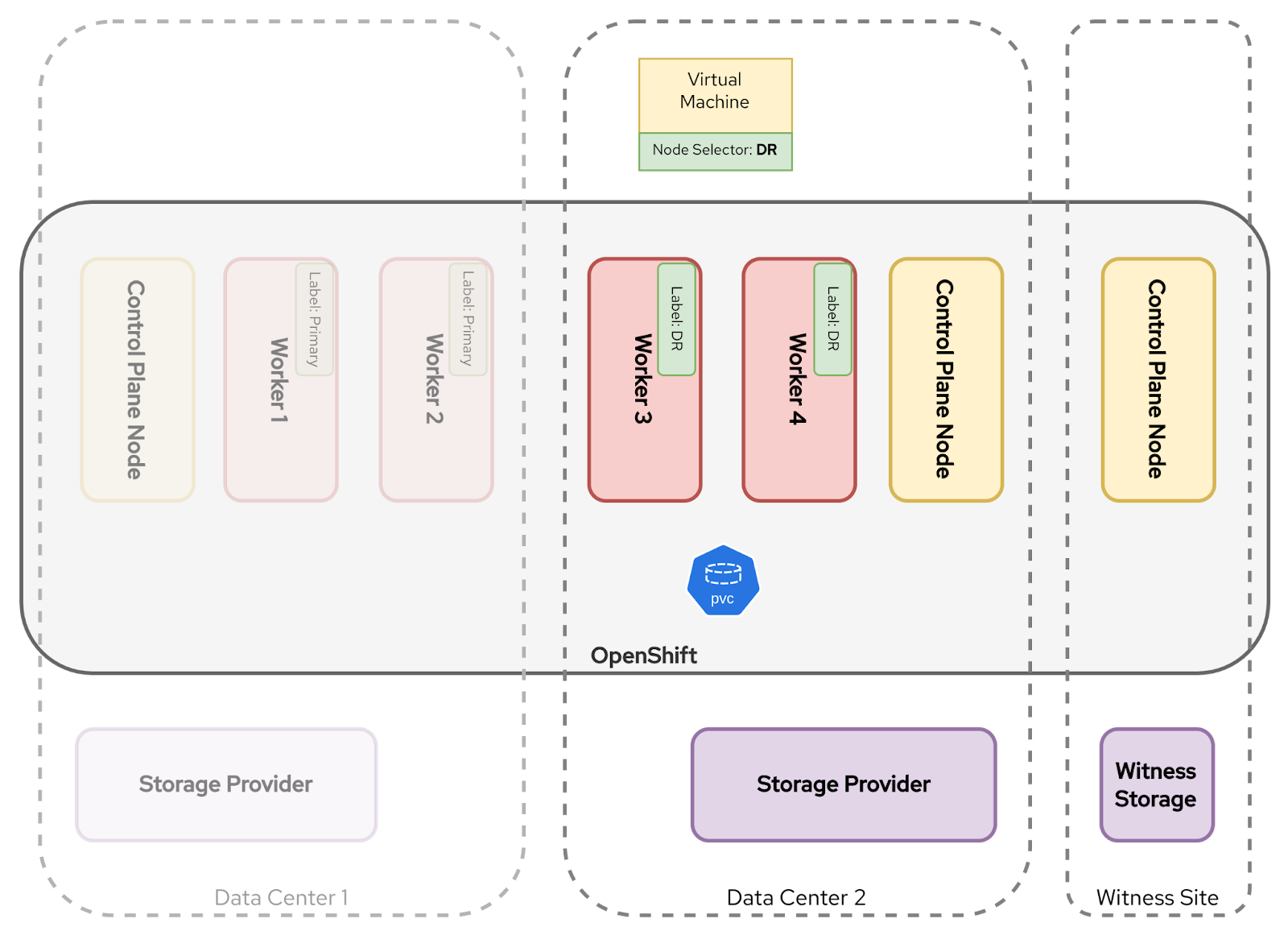
In the event of a disaster, all worker nodes in the Primary site will be lost. The VMs will be unschedulable because the KubeVirt scheduler cannot find a node with a matching label. But unlike the multicluster topology pattern, the VM is already defined in the cluster. This means that failover is affected by a single change to the node selector rule used by the VM template.
To trigger a failover, a patch is applied to the node selector from Primary to DR:
spec:
  template:
    spec:
      nodeSelector:
        topology.kubernetes.io/site: DR
Another option is to remove the node selector entirely, thereby removing the constraint. However, the complication with removing it is that, for all the reasons described above, you lose complete control of the fail back.
As illustrated in Figure 4, the Kubernetes scheduler will then recreate the VM pod on workers in the healthy site. Stretched storage handles the disk re‑attachment transparently.

Streamlining application failover design and implementation
Having described the essential process for application failover, we turn our attention to some good practices for a GitOps-first approach to designing, implementing, and executing disaster recovery.
The primary goal of disaster recovery is to recover services as quickly and reliably as possible. With that in mind, a good philosophy is to maximize the use of Kubernetes features and Kubernetes-native tooling. In doing so, you minimize the need for complex orchestration, bespoke automation solutions, and manual processes—all of which come with increased cost, complexity, and operational risk.
The following four practices align with the philosophy above:
- Describe all of the DR states declaratively.
- Describe the stages of the DR orchestration state as a delta (difference) from one another.
- Prefer purpose-built GitOps controllers over bespoke automation.
- Ensure that you always have a "break glass" option.
Let's explore these in more detail.
Good practice 1: Describe both the BAU and DR states declaratively
Disaster recovery processes are most resilient when they are declarative—that is, when they express what should happen, not how it should be done. In Kubernetes environments, this declarative approach aligns naturally with GitOps methodologies, where both the business as usual (BAU) and DR configurations are stored as version-controlled manifests. By describing both states declaratively, you ensure that your failover strategy benefits from the same consistency, auditability, and repeatability that Kubernetes provides for routine operations.
Declarative state descriptions provide a single source of truth, enforceable by GitOps controllers. These controllers reconcile the actual cluster state to match the declared desired state (whether it be BAU or DR) without manual intervention. When an incident occurs, failover becomes a controlled reapplication of a known-good manifest. Moreover, the ability to simulate or test the DR configuration prior to a real failure becomes more feasible, as DR manifests can be validated using dry-run deployments on lower environments.
In practice, this means encoding all site-specific scheduling logic, storage attachments, network policies, and DNS overrides in Kubernetes-native YAML. Then, placing those definitions under version control. A GitOps controller observes changes and applies them automatically to the cluster, shifting workloads into the desired state. This approach removes ambiguity, reduces the opportunity for error during stressful incident conditions and enables DR rehearsals to be executed with confidence and precision.
Good practice 2: Describe the DR state as a delta of the BAU state
With both the BAU and DR states expressed declaratively, the next step is to avoid duplication by describing the DR state as a delta (i.e., a concise difference) of the BAU configuration. The principal advantage of describing DR as a delta is that it simplifies validation. Reviewers do not need to examine an entire deployment manifest. Instead, they only need to verify that the changes made during a failover are valid, complete and correct. This clarity reduces cognitive burden, limits configuration drift and supports repeatable rehearsals. Git becomes the canonical record. Each change, however minor, is visible, revertible and attributable.
Kubernetes-native tooling, such as Kustomize and Helm, make this delta-based approach both practical and idiomatic. With Kustomize, for example, a common base directory that describes the standard deployment is defined, and an overlays/dr directory, for example, that applies minimal, scoped patches to alter site-specific details such as Node Selectors, replica counts, or annotations represents the changes needed to support deployment to a DR site. Kustomize renders a full manifest by merging the overlay onto the base, ensuring consistency while isolating DR-specific logic.
Helm supports the same concept through a set of templated manifests and parameterized values.yaml files. A shared Helm chart can be reused across both BAU and DR environments, with minor overrides applied through a separate values-dr.yaml file. As with Kustomize, this model allows for tight control over changes and offers a clear, auditable diff between the two states.
Good practice 3: Prefer purpose-built GitOps controllers over bespoke automation
When implementing disaster recovery, leaning on Kubernetes-native control planes and GitOps workflows delivers greater long-term reliability than building bespoke automation. Purpose-built controllers, such as Argo CD, Flux, and Red Hat Advanced Cluster Management, are designed to manage application placement and policy reconciliation declaratively, securely, and at scale. These controllers reduce operational complexity through built-in drift detection, role-based access control (RBAC) integration, metrics for observability, and consistent behavior across environments. These are features that are difficult and costly to replicate in custom scripts.
The choice of control plane depends in part on the cluster topology. In a multicluster topology, the control plane must handle redeployment across clusters. This is typically achieved through a combination of GitOps tooling and placement logic. GitOps controllers, like Argo CD, observe changes in a shared Git repository and apply manifests to the recovery cluster. Red Hat Advanced Cluster Management complements this approach by managing Placement objects. When a disaster strikes, updating a Placement rule shifts the entire workload from the primary to the DR cluster in a declarative, observable, and fully auditable way.
In a single-cluster topology, disaster recovery is a matter of redirecting workloads within the same control plane. DR becomes an intra-cluster placement activity. Instead of managing the deployment across clusters, the controller’s job is to update in-cluster scheduling logic.
GitOps controllers are well-suited to this task, continuously reconciling the desired scheduling logic and enforcing placement rules through declarative resources. In practice, this means adjusting site-specific selectors, taints, or affinity rules in a Git repository. The controller observes the update, applies the patch and verifies compliance across the cluster. This model preserves the core strengths of Kubernetes—idempotence, observability, and repeatability—while eliminating the need for bespoke scripting.
Policy-driven solutions, such as Red Hat Advanced Cluster Management control this process through its Governance framework, where ConfigurationPolicy resources enforce site-specific settings, like Node Selectors. Changing a single field in the policy is enough to relocate every VM to the DR site. Red Hat Advanced Cluster Management then verifies compliance and provides visibility into which workloads have been successfully moved.
Additionally, some advanced storage platforms integrate natively with Kubernetes and GitOps workflows, providing APIs or Custom Resource Definitions (CRDs) that allow failover to be triggered declaratively. When these platforms also replicate application metadata alongside volumes, they can serve as a hybrid control plane—combining storage awareness with policy-driven automation.
By relying on these native controllers, organizations benefit from tools that are battle-tested, integrated into the Kubernetes ecosystem, and can be independently security reviewed.
Good practice 4: Ensure that you always have a "break glass" option
Even the best DR plans must account for control-plane unavailability. In particular, a Git repository or GitOps controller may be unreachable during a site outage. A "break glass" option ensures that a failover can still be initiated using manual tools while maintaining compatibility with your Git-driven workflow.
For GitOps-driven systems, a common practice renders the failover manifests locally and applies them directly via command line tools. This implies that a copy of the Git repository resides locally. For example, using Kustomize, you can use the following command to apply the configurations to failover to a DR site:
oc apply -k overlays/drSimilarly, with Helm you can render and apply the DR-specific values file:
helm template my-release ./chart -f values-dr.yaml | oc apply -f -These manual commands bypass the GitOps controller, but still apply the same declarative changes, enabling a consistent and predictable failover, even in degraded conditions.
By adopting this practice, you will turn the unexpected into a manageable operational step and ensure that disaster recovery remains possible under the most challenging conditions.
Conclusion
Disaster recovery for virtual machines on Red Hat OpenShift begins with one foundational decision: the choice of cluster and storage architecture. Whether opting for a stretched cluster with symmetric replication or a dual-cluster design with unidirectional replication, this architecture shapes every downstream decision about how failover will be executed. It dictates what recovery point objective (RPO) and recovery time objective (RTO) targets are feasible, what automation can be safely applied, and how much operational complexity must be absorbed by the platform versus the service-operations team.
The focus then shifts to defining workload placement and failover logic declaratively, enabling a seamless handoff between infrastructure capabilities and application orchestration. Kubernetes-native primitives, GitOps workflows, and tools like Red Hat Advanced Cluster Management allow these definitions to be automated, audited, and tested in advance. But their effectiveness is bounded by the underlying architecture. A robust disaster recovery strategy, therefore, is not just about the VMs or manifests; it is an end-to-end alignment of topology, storage behavior, and operational design.
