This article describes an architectural model for executing Red Hat Ansible Automation Platform automations in a hybrid environment where a cloud-hosted management cluster controls on-premise bare-metal Red Hat OpenShift Virtualization clusters hosting critical virtual machines (VM).
This proposed approach eliminates the need for dedicated execution nodes. It fully leverages the cloud-native capabilities of Ansible deployed using an operator, delegating the dynamic management of automation workloads to Kubernetes. Specifically, automations are executed through execution environments scheduled directly on the target OpenShift Virtualization clusters, within the same namespace and network as the virtual machines being operated upon. This model enables an automation proximity mechanism, reducing latency and network dependency.
This solution avoids opening direct network channels from the management cluster to the VMs (for example, SSH), mitigating risk of intrusive policies and expanded attack surfaces. Automation orchestration instead relies on the existing connectivity between the management cluster and managed clusters using the Kubernetes API server, provided by the multicluster management framework.
The result is a distributed automation paradigm that separates control plane and execution plane, optimizes network traffic, and enables secure and scalable operations on on-premise VMs while remaining fully aligned with the declarative model of Kubernetes and OpenShift.
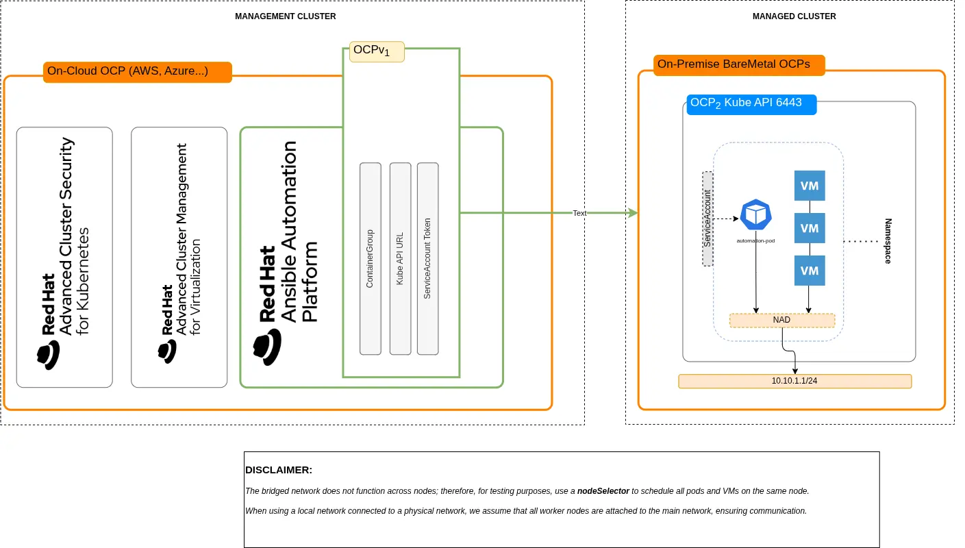
In this scenario, we aim to demonstrate a highly effective pattern (see Figure 1) for hybrid environments:
- Red Hat Ansible Automation Platform is installed on a management cluster (typically in the cloud), alongside other management and security tools (such as Red Hat Advanced Cluster Management for Kubernetes and Red Hat Advanced Cluster Security for Kubernetes).
- OpenShift Virtualization runs on bare-metal infrastructure on-premise, and hosts virtual machines.
- Automation workflows must not require opening network connectivity from the management cluster to the VMs (no SSH from cloud to on-prem).
- Execution environments (pods) are scheduled directly on the target cluster, close to the VMs, within the same namespace, leveraging the existing connectivity through the Kubernetes API server.
At least two environments are involved:
- Management cluster
- Managed cluster (OpenShift Virtualization)
Lab networking considerations
For the purpose of this example, the networking setup has been intentionally simplified to make the scenario easier to reproduce in a lab environment. In particular, this example implementation uses a bridged NetworkAttachmentDefinition (NAD) to connect workloads, instead of relying on localnet networks backed by physical infrastructure. While this approach differs from a production-ready design, it allows us to simulate network proximity and validate the automation pattern without requiring dedicated hardware, VLANs, or external routing components.
In a real-world deployment, localnet networks would typically be used to attach workloads directly to physical networks, often combined with external L3 routing to enable communication between different network segments. This ensures integration with existing data center networking, improved performance, and clear separation of concerns.
Despite this simplification, the core concepts demonstrated in this article remain unchanged: Automation is executed close to the target workloads, within the same cluster and network domain, minimizing latency and avoiding unnecessary external connectivity.
Working on OpenShift Virtualization (managed cluster) {#working-on-openshift-virtualization-(managed-cluster)}
The following operations refer to Instance and Container Group:
Labeling node
Because this demo uses a bridged network (CNI bridge), which is node-local, we enforce workload placement on a specific node for simplicity. Accessing the managed cluster through the oc login command, list all nodes:
$ oc get nodes
NAME                            STATUS   ROLES                  AGE   VERSION
control-plane-cluster-*******   Ready    control-plane,master   13d   v1.30.5
control-plane-cluster-*******   Ready    control-plane,master   13d   v1.30.5
control-plane-cluster-*******   Ready    control-plane,master   13d   v1.30.5
worker-cluster-5qpvg-1          Ready    worker                 13d   v1.30.5
worker-cluster-*******          Ready    worker                 13d   v1.30.5
worker-cluster-*******          Ready    worker                 13d   v1.30.5
Use the node worker-cluster-5qpvg-1 and label it:
$ oc label node worker-cluster-5qpvg-1 placement-node=node1In the next steps, I use the label placement-node=node1 for nodeSelector.
Creating required resources in the managed cluster
In this section, we create all required resources in the managed cluster:
- Namespace
- ServiceAccount
- Role
- RoleBinding
- ServiceAccount Token
- NAD
- VMS for testing purpose
First, create a new namespace when applying all resources, including VMs and remote pods. Create the file security01-namespace.yaml and paste in this content:
# security01-namespace.yaml
kind: Project
apiVersion: project.openshift.io/v1
metadata:
  name: security01
Apply the resource and create the namespace:
$ oc apply -f namespace.yamlServiceAccount
Next, create a ServiceAccount as required for authenticating the management cluster against on-premise bare-metal Openshift Virtualization cluster. Create a file named serviceaccount_bundle.yaml and paste in this content:
# serviceaccount_bundle.yaml
apiVersion: v1
kind: ServiceAccount
metadata:
  name: security-compliance-cg
  namespace: security01
---
kind: Role
apiVersion: rbac.authorization.k8s.io/v1
metadata:
  name: role-security-compliance-cg
  namespace: security01
rules:
  - verbs:
      - get
      - list
      - watch
      - create
      - update
      - patch
      - delete
    apiGroups:
      - ''
    resources:
      - pods
  - verbs:
      - get
    apiGroups:
      - ''
    resources:
      - pods/log
  - verbs:
      - create
    apiGroups:
      - ''
    resources:
      - pods/attach
  - verbs:
      - get
      - create
      - delete
    apiGroups:
      - ''
    resources:
      - secrets
---
kind: RoleBinding
apiVersion: rbac.authorization.k8s.io/v1
metadata:
  name: role-security-compliance-cg-binding
  namespace: security01
subjects:
- kind: ServiceAccount
  name: security-compliance-cg
  namespace: security01
roleRef:
  kind: Role
  name: role-security-compliance-cg
  apiGroup: rbac.authorization.k8s.io
Apply the resource and create the ServiceAccount, role, and role binding:
$ oc apply -f serviceaccount_bundle.yamlCreate a token for the ServiceAccount. This token is used by Red Hat Ansible Automation Platform. This command saves the token to a file:
$ oc create token security-compliance-cg \
--duration=$((365*24))h > security-compliance-cg.token
Creating the NetworkAttachmentDefinition
For the virtual machines to use this network, we must create a NetworkAttachmentDefinition. In this example scenario, the NAD uses a bridged network with whereabouts and a DHCP-like mechanism. Create a file named bridged_nad.yaml and paste in this content:
# bridged_nad.yaml
apiVersion: k8s.cni.cncf.io/v1
kind: NetworkAttachmentDefinition
metadata:
  name: vm-net
  namespace: security01
spec:
  config: |
    {
      "cniVersion": "0.3.1",
      "type": "bridge",
      "bridge": "br-vm",
      "ipam": {
        "type": "whereabouts",
        "range": "10.10.1.100-10.10.1.200/24",
        "gateway": "10.10.1.1"
      }
    }
This NetworkAttachmentDefinition operates with an IP range from 100 to 200, and is used by virtual machines and execution environments pods. Apply the resource and create NetworkAttachmentDefinition:
$ oc apply -f bridged_nad.yamlVirtual machines
To generate two virtual machines (running Fedora) from the Openshift Virtualization template, create one file named vm-security01.yaml and another named vm-security02.yaml. Paste in this content, replacing securityXX with security01 and security02 in the matching files, but leave the namespace as security01 in both files:
# vm-securityXX.yaml
apiVersion: kubevirt.io/v1
kind: VirtualMachine
metadata:
  name: securityXX
  namespace: security01
spec:
  dataVolumeTemplates:
    - metadata:
        name: securityXX-volume
      spec:
        sourceRef:
          kind: DataSource
          name: fedora
          namespace: openshift-virtualization-os-images
        storage:
          storageClassName: ocs-external-storagecluster-ceph-rbd
  instancetype:
    name: u1.medium
  preference:
    name: fedora
  running: true
  template:
    metadata:
      labels:
        network.kubevirt.io/headlessService: headless
    spec:
      nodeSelector:
        placement-node: node1
      domain:
        devices:
          autoattachPodInterface: false
          disks:
            - disk:
                bus: virtio
              name: cloudinitdisk
          interfaces:
            - bridge: {}
              model: virtio
              name: default
      networks:
        - name: default
          multus:
            networkName: vm-net
      subdomain: headless
      volumes:
        - dataVolume:
            name: securityXX-volume
          name: rootdisk
        - cloudInitNoCloud:
            userData: |
              #cloud-config
              chpasswd:
                expire: false
              password: fedora
              user: fedora

              write_files:
                - path: /usr/local/bin/fix-ssh.sh
                  permissions: '0755'
                  owner: root:root
                  content: |
                    #!/bin/bash
                    set -e

                    FILE="/etc/ssh/sshd_config.d/50-cloud-init.conf"

                    for i in {1..10}; do
                      [ -f "$FILE" ] && break
                      sleep 1
                    done

                    sed -i 's/^PasswordAuthentication.*/PasswordAuthentication yes/' "$FILE"

                    grep -q "^PasswordAuthentication" "$FILE" || echo "PasswordAuthentication yes" >> "$FILE"

                    systemctl restart sshd

              runcmd:
                - /usr/local/bin/fix-ssh.sh
          name: cloudinitdisk
Both VirtualMachines have the following access parameters:
- Username:
fedora - Password:
fedora
SSH access is enabled on port 22 through the NetworkAttachmentDefinition vm-net. The `networks` section in each YAML file declares the network to be used, and it binds the NetworkAttachmentDefinition vm-net:
networks:
    - name: default
        multus:
        networkName: vm-net
The spec section declares the Red Hat OpenShift node used for placement:
spec:
    template:
        spec:
            nodeSelector:
                placement-node: node1
Important: Before provisioning virtual machines, verify the name of the storageClass to be used:
storage:
    storageClassName: ocs-external-storagecluster-ceph-rbd
Apply both resources and create the virtual machines:
$ oc apply -f vm-security01.yaml
$ oc apply -f vm-security02.yaml
Retrieving virtual machine IPs
Both VMs are configured to use the NetworkAttachmentDefinition vm-net with the whereabouts mechanism. To get the IP of each virtual machine, you have two options.
Option 1: Use Red Hat Openshift web console
In Red Hat Openshift console, verify that both VWs are up and running by navigating to the Administrator perspective > Virtualization > VirtualMachines. Select the project security01 from the drop-down menu. Two virtual machines are visible, as shown in Figure 2.
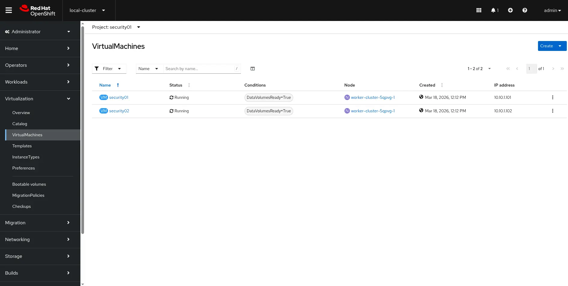
Click security01 to access its details, as in Figure 3:
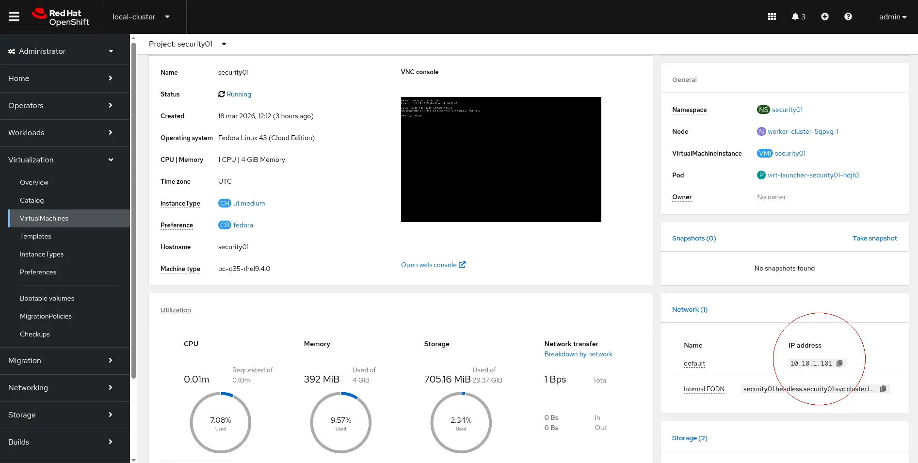
The IP address is in the Network section of the image.
Option 2: Use the oc command
You can get the IP address of a virtual machine using the oc command (replace the VM name as necessary for security02):
$ oc get vmi security01 -n security01 \
-o jsonpath='{.status.interfaces[0].ipAddress}'
The command returns an output like this:
10.10.1.101The IP addresses of your virtual machines will almost certainly differ from mine.
Working on Ansible (management cluster)
This procedure describes the creation of the following objects on Red Hat Ansible Automation Platform:
- Credential (Kubernetes / Red Hat OpenShift credential type)
- InstanceGroup (of type ContainerGroup)
- Inventory
- Adding hosts to inventory
- Project
- Job Template
Prerequisites
To complete this section, you must:
- Have access to the Red Hat Ansible Automation Platform web console
- Have Red Hat Ansible Automation Platform installed on an OpenShift instance that serves as a cluster manager of an OpenShift Virtualization cluster
Creating credentials
Create a credential to be used when connecting to a remote OpenShift cluster. First, access Red Hat Ansible Automation Platform and navigate to Automation Execution > Infrastructure > Credentials > Create Credential.
From the Credential type drop-down menu, select OpenShift or Kubernetes API Bearer Token. Fill the form with the following values:
- Name:
security01-cluster-credential - Organization: This is for your own reference, so use any value you prefer
- OpenShift or Kubernetes API Endpoint: Red Hat Openshift with OpenShift Virtualization (on-premises) API URL (listening on 6443)
- API authentication bearer token: Use the ServiceAccount token you generated earlier in this article
- Verify SSL: Disable
Click Create Credential to complete the task.
Creating an InstanceGroup
Navigate to Automation Execution > Infrastructure > Instance Groups > Create group > Create container group and enable Customize pod spec. Fill in the form:
- Name:
security01-IG - Credential: Assign the credential
security01-cluster-credential, which you created in the previous step.
Then replace the contents of Pod spec override with this (as shown in Figure 4):
apiVersion: v1
kind: Pod
metadata:
  namespace: security01
  labels:
    ansible_job: ''
  annotations:
    k8s.v1.cni.cncf.io/networks: security01/vm-net
spec:
  nodeSelector:
   placement-node: node1
  serviceAccountName: security-compliance-cg
  automountServiceAccountToken: false
  affinity:
    podAntiAffinity:
      preferredDuringSchedulingIgnoredDuringExecution:
        - weight: 100
          podAffinityTerm:
            labelSelector:
              matchExpressions:
                - key: ansible_job
                  operator: Exists
            topologyKey: kubernetes.io/hostname
  containers:
    - image: >-
        registry.redhat.io/ansible-automation-platform-26/ee-supported-rhel9@sha256:17be45bba90a79f439d4571f1c92331edfbb9a75efabd58d30ea5424bca8cee0
      name: worker
      args:
        - ansible-runner
        - worker
        - '--private-data-dir=/runner'
      resources:
        requests:
          cpu: 1
          memory: 2Gi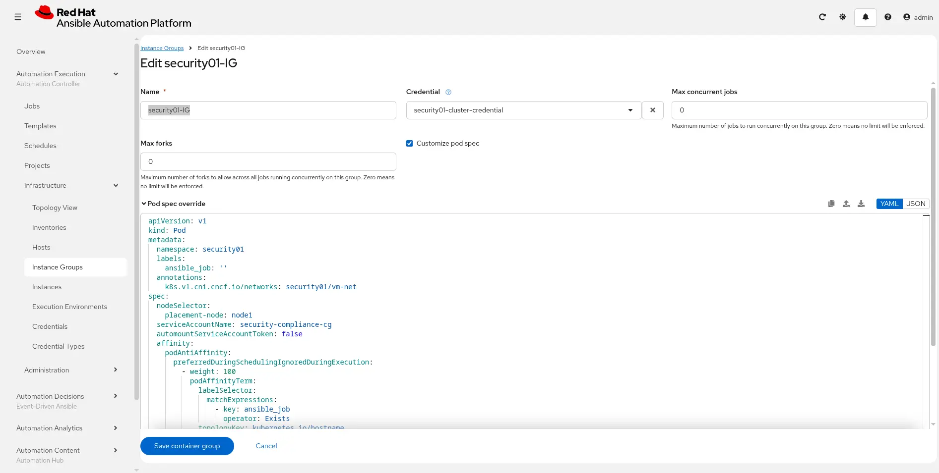
Note the following section, where we have defined serviceAccount, namespace, and NetworkAttachmentDefinition already prepared on the remote cluster:
apiVersion: v1
kind: Pod
metadata:
  namespace: security01
  labels:
    ansible_job: ''
  annotations:
    k8s.v1.cni.cncf.io/networks: security01/vm-net
spec:
  nodeSelector:
   placement-node: node1
  serviceAccountName: security-compliance-cg
[...]
Click the Save container group button to save changes.
Inventory creation
To create a standard inventory, navigate to Automation execution > Infrastructure > Inventories. Click the Create inventory button and then select Create Inventory from the drop-down menu. Fill the form with the following values:
- Name:
security01-inventory - Organization: This is for your own reference, so use any value you prefer
After the inventory has been created, click the Hosts tab on the same page, and then click the Create host button.
Fill in the form, adding the IP address of VMs running in remote your Openshift cluster.
- Name: 10.10.1.101 (use your VM IP address)
- Description:
security01(adjust for the applicable VM) - Enabled: Yes
- Variables:
ansible_user: fedoraandansible_password: fedora
Ansible project and job template
Define a new Ansible project with the type scm, and create a playbook:
- name: Create folder on remote host
  hosts: all
  gather_facts: false

  tasks:

    - name: Create folder 1
      ansible.builtin.file:
        path: "/home/fedora/{{ awx_job_id }}"
        state: directory

    - name: Print hostname
      ansible.builtin.command: hostname
This playbook creates a folder named with awx_job_id in /home/fedora. The playbook acts on all hosts, and it needs an inventory to work properly. You can download the playbook from my Git repository.
Project creation
Navigate to Automation execution > Projects and click the Create project button. Fill in the form:
- Name:
Ansible-Remote-Execution-Environment - Organization: This is for your own reference, so use any value you prefer.
- Source control type: Git
- Source control URL: Enter a valid Git repository address accessible over HTTP.
- Source control branch/tag/commit: Change if you need to switch to another branch. In this example, I use
mainso I've left the field empty. - Source control credential: The selected repository is public, so no credential is required. You must create a new one when using an authenticated repo.
- Update revision on launch: Enabled
Click the Save Project button to sync the project and to pull content from the Git repository.
Creating a job template
Navigate to Automation execution > Template. Click the Create template button, and then Create Job template. Fill in the form:
- Name: Automate on remote hosts
- Inventory:
security01-inventory - Project:
Ansible-Remote-Execution-Environment - Playbook:
create_folder.yaml - Instance groups:
security01-IG
Click the Save Job template button to save the template.
Launching the job
In this step, we execute an automation playbook over remote hosts (security01 and security02 VMs, specifically) running on a remote OpenShift Virtualization cluster. Ansible is installed and running on a cloud instance of OpenShift.
Both clusters can communicate over HTTPS and the API server. There are no SSH connections opened from cloud to on-premise cluster.
The automation pod il scheduled on a remote cluster and connects to the same virtual machine network to perform SSH operations.
Step 1
Using the oc command, connect to your OpenShift Virtualization cluster and get a status report:
$ oc get po -n security01 -w
NAME                         READY STATUS  RESTARTS AGE
virt-launcher-sec..01-6lq4s   1/1  Running 0   63m
virt-launcher-sec..02-fntcm   1/1  Running 0   63m
Initial reports are on virt-launcher pods. Ignore them, because our automation works with VMs, not with these pods. Wait a while, and pods will show up.
Next, access Red Hat Ansible Automation Platform. Navigate to the previously created jobTemplate, and click on the Launch Template button. You see output similar to Figure 5:
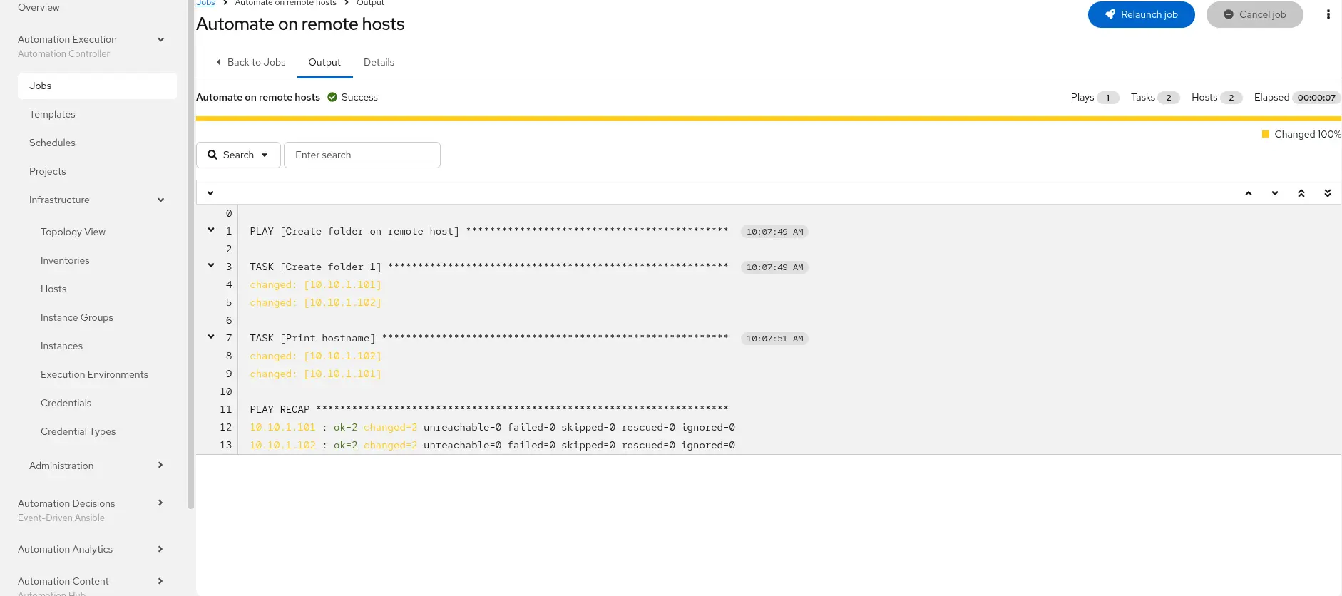
From the command-line, the output looks like this:
NAME                        READY STATUS RESTARTS   AGE
virt-launcher-sec..01-6lq4s  1/1  Running   0      69m
virt-launcher-sec..02-fntcm  1/1  Running   0      69m
automation-job-67-85bxr      0/1  Pending   0       0s
automation-job-67-85bxr      0/1  Pending   0       0s
automation-job-67-85bxr      0/1  Pending   0       0s
automation-job-67-85bxr      0/1  ContainerCreating 0s
automation-job-67-85bxr      0/1  ContainerCreating 0s
automation-job-67-85bxr      1/1  Running           1s
automation-job-67-85bxr      1/1  Terminating       6s
automation-job-67-85bxr      0/1  Terminating       7s
automation-job-67-85bxr      0/1  Terminating       7s
automation-job-67-85bxr      0/1  Terminating       7s
The sample playbook is designed to create a new folder on a remote VM, so let's verify what happened inside the virtual machine. From the OpenShift Virtualization web console, activate the Administrator perspective.
Navigate to Virtualization > VirtualMachines, and then click the security01 VM. Select Open web console to be placed into the VM shell, in /home/fedora.
We expect to find a folder with the same name as the Red Hat Ansible Automation Platform job ID. Type ls and verify that you see a folder with the same name as job ID. For example, it's 67 in this output:
Fedora Linux 43 (Cloud Edition)
Kernel 6.17.1-300.fc43.x86_64 on x86_64 (tty1)

enp1s0: 10.10.1.102 fe80::a2:90ff:fe00:16
Try contacting this VM's SSH server via 'ssh vsockx1' from host.

security01 login: fedora
Password:
[systemd]
Failed Units: 1
  dnf-makecache.service
[fedora@security01 ~]$ ls
55  56  58  59  65  67
[fedora@security01 ~]$ _
Networking model and execution flow
To summarize, for this methodology:
- No external SSH exposure is required
- The environment is prepared on both clusters
- Ansible creates a container group
- The pod job is scheduled on the managed cluster
- Ansible connects to VMs using vm-net NetworkAttachmentDefinition
Enterprise network topology
A testing environment is different from production. This section describes a production-grade networking architecture in OpenShift that integrates:
- Pod workloads
- Virtual machine workloads (via KubeVirt)
- Multiple physical networks
- External L3 routing
This design leverages localnet networks provided by OVN-Kubernetes to connect workloads directly to physical infrastructure. Figure 6 provides an architectural diagram.
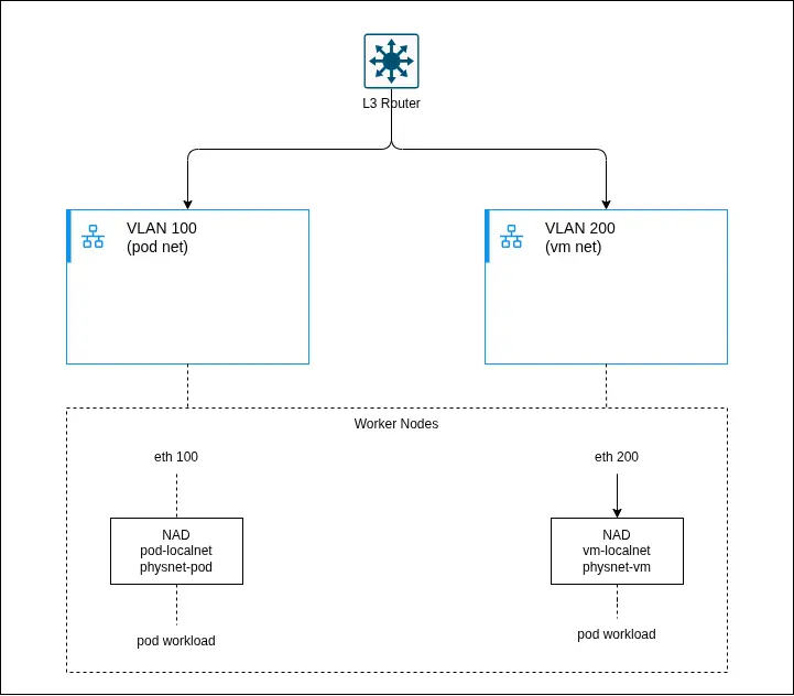
These are the components included:
- L3 router: Provides routing between VLANs/subnets (for example, a pod network and VM network). Acts as the default gateway for all workloads.
- Type: Network infrastructure
- OSI layer: L3
- VLAN 100 (pod network): Dedicated Layer 2 segment for pod workloads. Mapped to worker node interfaces (for example,
eth0.100).- Type: Physical network
- OSI layer: L2
- VLAN 200 (VM network): Dedicated Layer 2 segment for VM workloads. Typically used for external or legacy integrations.
- Type: Physical network
- OSI layer: L2
- Worker nodes: Host the workloads and provide connectivity to physical networks over VLAN interfaces.
- Type: Compute
- OSI layer: L1–L2
- pod-localnet NAD: A
localnetNetworkAttachmentDefinition mapping OVN to the pod physical network (physnet-pod).- Type: Network (CNI)
- OSI layer: L2
- vm-localnet NAD: A
localnetNetworkAttachmentDefinition mapping OVN to the VM physical network (physnet-vm).- Type: Network (CNI)
- OSI layer: L2
- physnet (OVN mapping): Logical mapping between OVN and host interfaces (for example,
physnet-podandeth0.100).- Type: OVN abstraction
- OSI layer: L2
- Pod workloads: Containerized applications attached to pod-localnet.
- Type: Application
- OSI layer: L7
- VM Workloads
- Type: Application
- Layer (OSI): L2–L7
- Description: Virtual machines managed via KubeVirt, attached to vm-localnet.
- OVN Integration Bridge (br-int): Open vSwitch bridge that forwards traffic between workloads and physical interfaces.
- Type: Virtual switch
- Layer (OSI): L2
- veth pairs: Connect pod network namespaces to the host networking stack.
- Type: Virtual link
- OSI layer: L2
Conclusion
This architecture enables a fundamentally different approach to automation in hybrid environments by shifting execution closer to where workloads actually run.
First, it improves security by eliminating the need to expose SSH access from the management cluster to on-premise virtual machines. Instead, all interactions are mediated through the Kubernetes API server, reducing the attack surface and avoiding complex and invasive network policies.
Second, it introduces the concept of execution proximity, where automation tasks are executed directly within the target cluster, in the same namespace and network context as the virtual machines. This not only reduces latency and network dependency but also ensures more predictable and reliable automation outcomes.
Additionally, the solution fully embraces a cloud-native, Kubernetes-based execution model. By leveraging container groups and dynamically scheduled pods, it removes the need for traditional execution nodes and aligns automation workflows with modern orchestration paradigms.
Overall, this pattern represents a scalable, secure, and operationally efficient approach to automation. It is particularly well suited for hybrid scenarios, where maintaining strict network boundaries and minimizing connectivity requirements are critical design goals.