Editor's note
This post was originally published in October 2018 and has been fully updated to reflect current Linux networking standards.
Linux provides rich virtual networking capabilities that provide the basis for hosting virtual machines (VMs), containers, and cloud environments. This guide introduces common virtual network interface types. We will focus on how to use these interfaces on Linux without deep code analysis. If you have a networking background, you might find this post useful. Run ip link help to see all available interfaces.
This post covers common interfaces and clarifies those that are often confused with one another:
- Bridge
- Bonded interface
- VLAN (Virtual LAN)
- VXLAN (Virtual eXtensible Local Area Network)
- MACVLAN
- IPVLAN
- MACVTAP/IPVTAP
- MACsec (Media Access Control Security)
- VETH (Virtual Ethernet)
- Netkit device
- VCAN (Virtual CAN)
- VXCAN (Virtual CAN tunnel)
- IPOIB (IP-over-InfiniBand)
- NLMON (NetLink MONitor)
- Netconsole interface
- Dummy interface
- Blackhole interface
- IFB (Intermediate Functional Block)
- netdevsim
This article explains what these interfaces are, how they differ, and how to create them. For tunnel interfaces, read An introduction to Linux virtual interfaces: Tunnels.
Bridge
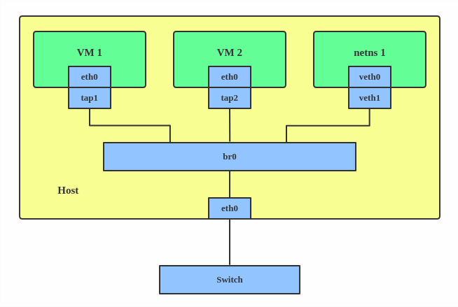
A Linux bridge works like a network switch to forward packets between interfaces (Figure 1). It's commonly used for packet forwarding on routers and gateways or between VMs and network namespaces on a host. It supports the Spanning Tree Protocol (STP), VLAN filtering, and multicast snooping.
When to use a bridge
Use a bridge when you need to connect multiple virtual interfaces (like VMs or containers) to each other or to a physical network as if they were on the same physical switch.
Creating a Linux bridge
Use the ip link command to create a bridge:
# ip link add br0 type bridge
# ip link set br0 up
To add a port to the bridge:
# ip link set eth0 master br0Spanning Tree Protocol (STP)
The Spanning Tree Protocol (STP) creates a loop-free logical topology for Ethernet networks to prevent bridge loops and broadcast storms. The Linux bridge supports Rapid Spanning Tree Protocol (RSTP) and Multiple Spanning Tree Protocol (MSTP). Use the following command to enable STP on a bridge:
# ip link set br0 type bridge stp_state 1Multicast support
The Linux bridge driver supports multicast, which allows it to process Internet Group Management Protocol (IGMP) or Multicast Listener Discovery (MLD) messages to forward packets efficiently. It supports IGMPv2/IGMPv3 and MLDv1/MLDv2. To enable multicast snooping and send IGMP/MLD query messages:
# ip link set br0 mcast_snooping 1
# ip link set br0 mcast_querier 1
VLAN filtering
The Linux bridge can add VLAN tags for each port similar to a hardware switch. Run these commands to enable VLAN filtering and set VLAN ID 2 for ports:
# ip link set br0 type bridge vlan_filtering 1
# ip link set eth1 master br0
# bridge vlan add dev eth1 vid 2 pvid untagged
The pvid parameter adds VLAN 2 tags for untagged frames on ingress (incoming traffic). The untagged parameter drops VLAN 2 tags on egress (outgoing traffic).
Additional resources
Use the ip link help bridge command or the ip-link man page for more information on STP and multicast parameters. For more on VLAN usage, run bridge help or man bridge.
The Linux bridge also supports modifying the forwarding database (FDB) and multicast group database (MDB) entries. Other features include MAC Authentication Bypass (MAB), IEEE 802.11 Proxy ARP, and switchdev. To learn more, refer to the bridge man page and the kernel bridge documentation.
Bonded interface
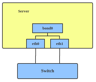
The Linux bonding driver aggregates multiple network interfaces into one logical bonded interface, as shown in Figure 2. Its behavior depends on the selected mode, which typically provides hot standby or load balancing services.
When to use a bonded interface
Use a bonded interface when you want to increase link speed or enable failover on a server.
Creating a bonded interface
Here's how to create a bonded interface:
ip link add bond1 type bond miimon 100 mode active-backup
ip link set eth0 master bond1
ip link set eth1 master bond1
These commands create a bonded interface named bond1 using the active-backup mode. For other modes, see the kernel documentation.
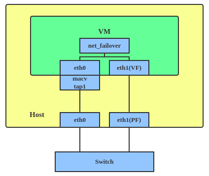
The net_failover driver is another failover primary net device for virtualization. It manages a primary device, such as a pass-through or virtual function (VF) device, and a standby paravirtual interface (Figure 3).
VLAN
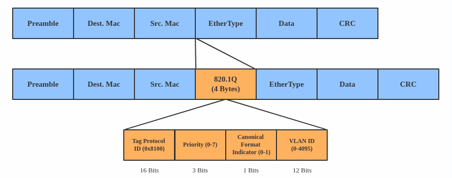
A virtual LAN (VLAN) separates broadcast domains by tagging network packets. VLANs allow network administrators to group hosts under the same switch or between different switches.
Figure 4 shows a standard VLAN header.
When to use a VLAN
Use a VLAN to separate subnets in VMs, namespaces, or hosts.
Creating a VLAN
Here's how to create a VLAN:
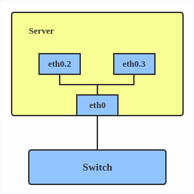
# ip link add link eth0 name eth0.2 type vlan id 2
# ip link add link eth0 name eth0.3 type vlan id 3
This adds VLAN 2 with name eth0.2 and VLAN 3 with name eth0.3. The topology is illustrated in Figure 5.
Note
When configuring a VLAN, ensure the switch connected to the host can handle VLAN tags. For example, set the switch port to trunk mode.
VXLAN
VXLAN (Virtual eXtensible Local Area Network) is a tunneling protocol that overcomes the 4,096 VLAN ID limit in IEEE 802.1Q. IETF RFC 7348 describes this protocol.
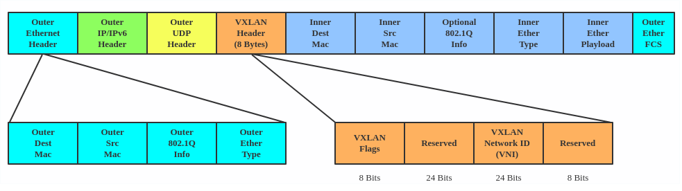
VXLAN uses a 24-bit segment ID called a VXLAN network identifier (VNI). This supports up to 16,777,216 virtual LANs. That's 4,096 times the capacity of a standard VLAN.
VXLAN encapsulates Layer 2 frames with a VXLAN header into a UDP-IP packet, as shown in Figure 6.
When to use VXLAN
Use VXLAN when you need to scale beyond 4,096 VLANs or when you need to create a Layer 2 overlay network across a Layer 3 infrastructure, such as in large-scale cloud environments.
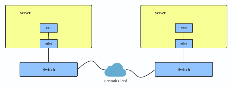
VXLAN is typically deployed in datacenters on virtualized hosts spread across multiple racks (Figure 7).
Creating a VXLAN
Here's how to use VXLAN:
# ip link add vx0 type vxlan id 100 local 1.1.1.1 remote 2.2.2.2 dev eth0 dstport 4789
For reference, you can read the VXLAN kernel documentation or this VXLAN introduction.
MACVLAN
With VLAN, you can create multiple interfaces on top of a single one and filter packages based on a VLAN tag. With MACVLAN, you can create multiple interfaces with different Layer 2 (that is, Ethernet MAC) addresses on top of a single one.
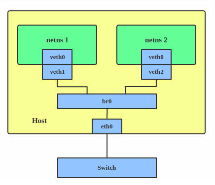
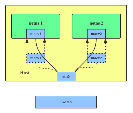
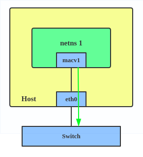
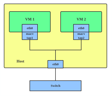
Before MACVLAN, connecting a VM or namespace to a physical network required creating TAP or VETH devices and attaching them to a bridge alongside a physical interface, as shown in Figure 8.
With MACVLAN, you can bind a physical interface directly to namespaces without using a bridge (Figure 9).
There are five MACVLAN types:
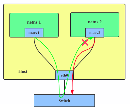
Private: This mode prevents communication between MACVLAN instances on the same physical interface, even if the external switch supports hairpin mode. See Figure 10.

Figure 10: In MACVLAN private mode, communication between local virtual interfaces is prohibited, even if they share the same physical eth0 device. VEPA: Data from one MACVLAN instance to the other on the same physical interface is transmitted over the physical interface (Figure 11). Either the attached switch needs to support hairpin mode or there must be a TCP/IP router forwarding the packets in order to allow communication.
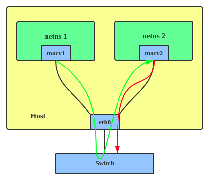
Figure 11: In Virtual Ethernet Port Aggregator (VEPA) mode, traffic between MACVLAN instances on the same physical interface must be reflected back by an external switch. Bridge: All endpoints are directly connected to each other with a simple bridge via the physical interface (Figure 12).
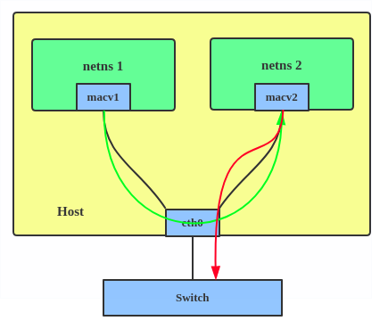
Figure 12: In MACVLAN bridge mode, virtual interfaces on the same physical device can communicate directly with each other without traffic leaving the host. Passthru: This mode connects a single VM directly to the physical interface (Figure 13).

Figure 13: In MACVLAN passthru mode, a single virtual interface is bound directly to the physical eth0 device, providing near-native performance for a single guest. - Source: The source mode is used to filter traffic based on a list of allowed source MAC addresses to create MAC-based VLAN associations. Refer to the commit message.


Choose a type based on your needs. Bridge mode is the most common.
When to use MACVLAN
Use a MACVLAN when you want to connect directly to a physical network from containers.
Creating a MACVLAN
Here's how to set up a MACVLAN:
# ip link add macvlan1 link eth0 type macvlan mode bridge
# ip netns add net1
# ip link set macvlan1 netns net1
This creates a new MACVLAN device in bridge mode and assigns this device to a network namespace.
IPVLAN
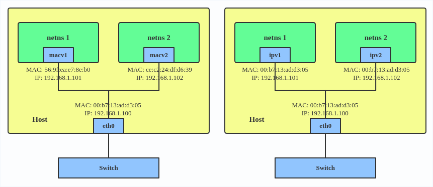
IPVLAN is similar to MACVLAN, but its endpoints share the same MAC address (Figure 14).
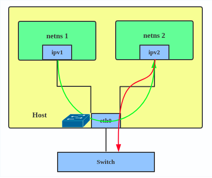
IPVLAN supports L2 and L3 mode. IPVLAN L2 mode acts like a MACVLAN in bridge mode. The parent interface looks like a bridge or switch. See Figure 15.
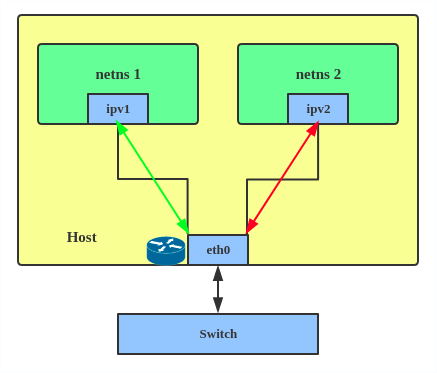
In IPVLAN L3 mode, the parent interface acts like a router and packets are routed between endpoints (Figure 16), which gives better scalability.
When to use IPVLAN
The IPVLAN kernel documentation says that MACVLAN and IPVLAN are very similar in many regards and the specific use case could very well define which device to choose. If any of the following situations apply to your use case, use IPVLAN:
- The Linux host connected to the external switch or router has a policy that allows only one MAC address per port.
- The number of virtual devices on a primary interface exceeds its MAC capacity and puts the NIC in promiscuous mode and degraded performance is a concern.
- If the secondary device is in an untrusted network namespace where L2 settings could be misused.
Creating an IPVLAN
Here's how to set up an IPVLAN instance:
# ip netns add ns0
# ip link add name ipvl0 link eth0 type ipvlan mode l2
# ip link set dev ipvl0 netns ns0
This creates an IPVLAN device named ipvl0 in L2 mode and assigns it to the ns0 namespace.
MACVTAP/IPVTAP
The MACVTAP and IPVTAP device drivers simplify virtualized bridged networking. When you create an instance, the kernel generates a character device at /dev/tapX. You can use this like a TUN/TAP device for KVM or QEMU.
MACVTAP and IPVTAP replace the need for separate TUN, TAP, and bridge drivers with one module.
When to use MACVTAP
Typically, MACVLAN/IPVLAN is used to make both the guest and the host show up directly on the switch to which the host is connected. The difference between MACVTAP and IPVTAP is same as with MACVLAN/IPVLAN.
Creating a MACVTAP instance
Here's how to create a MACVTAP instance:
# ip link add link eth0 name macvtap0 type macvtap
MACsec
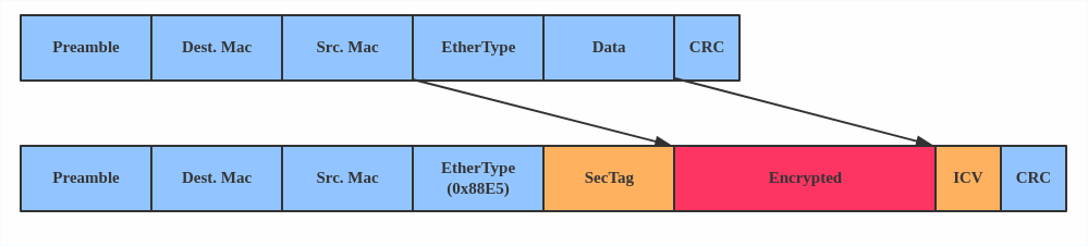
Media access control security (MACsec) is an IEEE standard for security in wired Ethernet LANs. Similar to IPsec, MACsec is a Layer 2 specification that protects IP traffic, Address Resolution Protocol (ARP), neighbor discovery, and Dynamic Host Configuration Protocol (DHCP). The MACsec headers look like this:
When to use MACsec
The main use case for MACsec is to secure all messages on a standard LAN including ARP, NS, and DHCP messages.
Creating a MACsec configuration
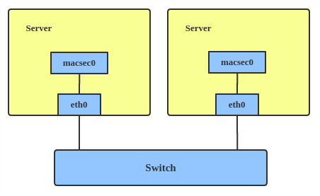
Here's how to set up a MACsec configuration:
# ip link add macsec0 link eth1 type macsecNote
This only adds a MACsec device called macsec0 on interface eth1. For more detailed configurations, see the Configuration example section in this MACsec introduction by Sabrina Dubroca.
VETH
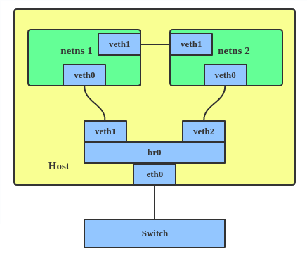
The VETH (virtual Ethernet) device is a local Ethernet tunnel. Devices are created in pairs, as shown in Figure 20.
Packets transmitted on one device in the pair are immediately received on the other device. When either device is down, the link state of the pair is down.
When to use VETH
Use a VETH configuration when namespaces must communicate with each other or the main host namespace.
Creating a VETH configuration
Here's how to set up a VETH configuration:
# ip netns add net1
# ip netns add net2
# ip link add veth1 netns net1 type veth peer name veth2 netns net2
This creates two namespaces, net1 and net2, and a pair of VETH devices, and it assigns veth1 to namespace net1 and veth2 to namespace net2. These two namespaces are connected with this VETH pair. Assign a pair of IP addresses, and you can ping and communicate between the two namespaces.
Netkit
The Netkit device is a minimal, BPF-programmable network device. It executes BPF programs during transmission to enable earlier packet processing. This is particularly useful for container/Pod networking, moving BPF execution closer to the source, which could improve egress traffic handling.
When to use Netkit
Use Netkit when you need BPF-programmable networking for containers to improve the efficiency of egress traffic handling.
Creating a Netkit device
Like a VETH device, the Netkit device is also implemented as a pair of devices (primary and peer). The primary device (hostns) manages BPF programs for itself and its peer. The peer device (container/Pod) cannot attach/detach BPF programs. The default policies can be set to 'pass' or 'drop' if no BPF program is attached.
By default, new devices use forwarding mode:
# ip link add type netkit
# ip -d a
[...]
7: nk0@nk1:  mtu 1500 qdisc noop state DOWN group default qlen 1000
  link/ether 00:00:00:00:00:00 brd ff:ff:ff:ff:ff:ff promiscuity 0 allmulti 0 minmtu 68 maxmtu 65535
  netkit mode l3 type peer policy forward numtxqueues 1 numrxqueues 1 [...]
8: nk1@nk0:  mtu 1500 qdisc noop state DOWN group default qlen 1000
  link/ether 00:00:00:00:00:00 brd ff:ff:ff:ff:ff:ff promiscuity 0 allmulti 0 minmtu 68 maxmtu 65535
  netkit mode l3 type primary policy forward numtxqueues 1 numrxqueues 1 [...]
Here is an example usage with netns:
# ip netns add blue
# ip link add nk0 type netkit peer nk1 netns blue
# ip link set up nk0
# ip addr add 10.0.0.1/24 dev nk0
# ip -n blue link set up nk1
# ip -n blue addr add 10.0.0.2/24 dev nk1
# ping -c1 10.0.0.2
PING 10.0.0.2 (10.0.0.2) 56(84) bytes of data.
64 bytes from 10.0.0.2: icmp_seq=1 ttl=64 time=0.021 ms
It also supports L2 mode. For example:
# ip link add foo type netkit mode l2 forward peer blackhole bar
# ip -d a
[...]
13: bar@foo:  mtu 1500 qdisc noop state DOWN group default qlen 1000
   link/ether 5e:5b:81:17:02:27 brd ff:ff:ff:ff:ff:ff promiscuity 0 allmulti 0 minmtu 68 maxmtu 65535
   netkit mode l2 type peer policy blackhole numtxqueues 1 numrxqueues 1 [...]
14: foo@bar:  mtu 1500 qdisc noop state DOWN group default qlen 1000
   link/ether de:01:a5:88:9e:99 brd ff:ff:ff:ff:ff:ff promiscuity 0 allmulti 0 minmtu 68 maxmtu 65535
   netkit mode l2 type primary policy forward numtxqueues 1 numrxqueues 1 [...]
VCAN
Similar to network loopback devices, the VCAN (virtual CAN) driver provides a virtual local CAN (Controller Area Network) interface that allows you to send and receive messages. Today, CAN is primarily used in the automotive industry.
See the kernel CAN documentation for more protocol information.
When to use VCAN
Use VCAN when you want to test a CAN protocol implementation on the local host.
Creating a VCAN
Here's how to create a VCAN:
# ip link add dev vcan1 type vcan
VXCAN
Like the VETH driver, a VXCAN (virtual CAN tunnel) creates a local CAN traffic tunnel between two VCAN network devices. Creating a VXCAN instance generates a pair of devices. When one device receives a packet, it appears on the paired device. VXCAN can be used for cross-namespace communication.
When to use VXCAN
Use a VXCAN configuration when you want to send CAN messages across namespaces.
Creating a VXCAN instance
Here's how to set up a VXCAN instance:
# ip netns add net1
# ip netns add net2
# ip link add vxcan1 netns net1 type vxcan peer name vxcan2 netns net2
Note: Red Hat Enterprise Linux does not currently support VXCAN.
IPOIB
An IPOIB device supports the IP-over-InfiniBand protocol, which transports IP packets over InfiniBand (IB) to use an IB device as a high-speed network interface card (NIC).
The IPOIB driver supports two modes: datagram and connected. In datagram mode, the IB unreliable datagram (UD) transport is used. In connected mode, the IB reliable connected (RC) transport is used. Connected mode uses the reliability of IB transport and supports a maximum transmission unit (MTU) of up to 64 KB. It allows a maximum transmission unit (MTU) up to the maximal IP packet size of 64K.
For more details, see the IPOIB kernel documentation.
When to use IPOIB
Use an IPOIB device when you have an IB device and want to communicate with a remote host via IP.
Creating an IPOIB device
Here's how to create an IPOIB device:
# ip link add ib0 name ipoib0 type ipoib pkey IB_PKEY mode connected
NLMON
NLMON is a Netlink monitor device.
When to use NLMON
Use an NLMON device when you want to monitor Netlink messages from the system.
Creating an NLMON device
Here's how to create an NLMON device:
# ip link add nlmon0 type nlmon
# ip link set nlmon0 up
# tcpdump -i nlmon0 -w nlmsg.pcap
This creates an NLMON device named nlmon0 and sets it up. Use a packet sniffer (for example, tcpdump) to capture Netlink messages. Recent versions of Wireshark feature decoding of Netlink messages.
netconsole interface
netconsole is a kernel module that captures and transmits kernel log messages (dmesg) over a network.
When to use netconsole
Use netconsole for debugging kernel crashes, freezes, or early boot issues, especially when local logging (such as a disk or serial console) is unavailable or has failed.
Creating a netconsole configuration
You can enable netconsole by loading the module with specific parameters or by adding it to the kernel command line. To create a configuration at runtime, use the following command:
# modprobe netconsole netconsole=@192.168.1.100/eth0,@192.168.1.200/6666
In this example, @192.168.1.100/eth0 represents the source IP address and interface, and @192.168.1.200/6666 represents the destination IP address and UDP port.
Configuring netconsole at runtime
To modify settings without reloading the module, use the /sys/module/netconsole/parameters/ path. For example, to change the remote target IP or port:
# Check existing settings
cat /sys/module/netconsole/parameters/*
# Change remote target IP
echo 192.168.1.200 > /sys/module/netconsole/parameters/remote_ip
# Change remote port
echo 6666 > /sys/module/netconsole/parameters/remote_port
Dummy interface
A dummy interface is entirely virtual, similar to a loopback interface. A dummy interface provides a way to route packets without transmitting them.
When to use a dummy interface
Use a dummy interface to make an inactive SLIP (Serial Line Internet Protocol) address look like a real address for local programs. Nowadays, a dummy interface is mostly used for testing and debugging.
Creating a dummy interface
Here's how to create a dummy interface:
# ip link add dummy1 type dummy
# ip addr add 1.1.1.1/24 dev dummy1
# ip link set dummy1 up
Blackhole
A blackhole interface is a virtual network device that silently discards packets. It functions like /dev/null for network traffic; any packet sent to it is dropped without a response or an error message.
When to use a blackhole interface
Use a blackhole interface for security, routing isolation, and performance management. It is particularly useful for stopping "denial of service" (DoS) attacks by discarding traffic from malicious IP ranges or for isolating internal traffic during complex routing configurations.
Creating a blackhole route
You can add a blackhole route using the ip route command to discard all traffic destined for a specific network:
# ip route add blackhole 192.168.1.0/24
Using blackhole in policy-based routing
You can also configure policy-based routing (PBR) with a blackhole to drop traffic originating from a specific source:
# ip rule add from 10.0.0.0/8 table 100
# ip route add blackhole default table 100
This ensures that all traffic originating from 10.0.0.0/8 will be dropped.
IFB
The intermediate functional block (IFB) driver concentrates traffic from multiple sources to shape it rather than dropping it.
When to use IFB
Use an IFB interface when you want to queue and shape incoming traffic.
Creating an IFB interface
Here's how to create an IFB interface:
# ip link add ifb0 type ifb
# ip link set ifb0 up
# tc qdisc add dev ifb0 root sfq
# tc qdisc add dev eth0 handle ffff: ingress
# tc filter add dev eth0 parent ffff: u32 match u32 0 0 action mirred egress redirect dev ifb0
This creates an IFB device named ifb0 and replaces the root qdisc scheduler with SFQ (Stochastic Fairness Queueing), which is a classless queueing scheduler. Then it adds an ingress qdisc scheduler on eth0 and redirects all ingress traffic to ifb0.
For more IFB qdisc use cases, refer to this Linux Foundation wiki on IFB.
Note
IFB devices are no longer common. Use tc qdisc clsact instead, which is the standard for packet classification and filtering.
netdevsim interface
The netdevsim device is a simulated networking device used to test various networking APIs.
When to use netdevsim
Use netdevsim to test networking features without requiring physical hardware. It is primarily used for testing hardware offloading, tc or XDP BPF programs, and Single Root I/O Virtualization (SR-IOV).
Creating a netdevsim device
To create a netdevsim device, load the module and echo the configuration (ID, port count, and number of queues) to the bus. The following example creates a device named netdevsim0 with two ports and four queues per port:
modprobe netdevsim
echo "0 2 4" > /sys/bus/netdevsim/new_device
You can verify the created ports and their hardware settings using ip link and ethtool:
# ls /sys/bus/netdevsim/devices/netdevsim0/net/
eni0np1 eni0np2
Testing hardware offloading
The netdevsim device supports several hardware offloads, such as TCP Segmentation Offload (TSO), Generic Segmentation Offload (GSO), and IPsec ESP. Use ethtool to verify these capabilities:
ethtool -k eni0np1 | grep espYou can also enable Traffic Control (tc) offload or load eXpress Data Path (XDP) BPF programs to verify offloading logic:
ethtool -K eni0np1 hw-tc-offload on
ip link set dev eni0np1 xdpoffload obj prog.o
Testing SR-IOV and devlink
To test Single Root I/O Virtualization (SR-IOV), you can add virtual functions (VFs) to the simulated device and assign them MAC addresses:
echo 2 > /sys/bus/netdevsim/devices/netdevsim0/sriov_numvfs
ip link set eni0np1 vf 0 mac 00:11:22:33:44:55
Use the devlink utility to inspect device information and resources, such as Forwarding Information Base (FIB) occupancy:
devlink dev info netdevsim/netdevsim0
devlink resource show netdevsim/netdevsim0
Note: netdevsim is not compiled in Red Hat Enterprise Linux by default.
Additional resources
- Virtual networking on the Red Hat Developer blog
- Dynamic IP Address Management in Open Virtual Network (OVN)
- Non-root Open vSwitch in Red Hat Enterprise Linux
- Open vSwitch on the Red Hat Developer blog
